|
| |
TM 5-4210-220-12
4-24. ELECTRICAL SYSTEM - Continued
4-24.4 Instrument Control Panel Instruments - Continued.
b.
Cab Air Panel Gages Replacement - Continued
(6)
Remove fittings from gage.
(7)
Install fitting on new gage. Coat pipe
threads with pipe sealant (item 22,
Appendix B) prior to installation.
(8)
Install new gage in panel. Ensure bezel
fits snugly against plate.
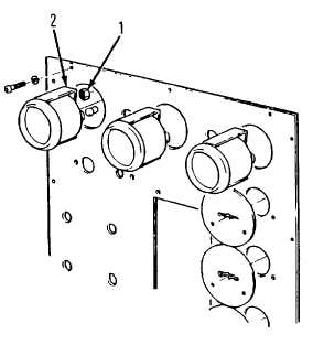
(9)
Install new nuts (1) and clamp (2).
Tighten nuts.
(10)
Connect air line to gage as tagged.
(11)
Aline dash panel on instrument panel
frame and install 12 machine screws.
(12)
Connect batteries and start main engine. Check pressure gages for correct readings as air system is
charged. When fully charged, all gages should indicate 105 - 110 psi (720 - 760 kPa).
c.
Cab Fold-down Panel Gages Replacement
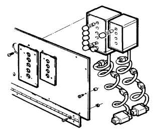
NOTE
This instruction details replacement of the level monitors and pressure gages on the cab fold-down panel.
(1)
Remove 10 machine screws from top and
sides of fold-down panel and pull panel
upwards from top.
(2)
To replace either level monitor, tag and
remove wires from monitor and remove 2
screws from bezel plate.
(3)
Lift off bezel and remove monitor.
(4)
Aline new monitor and bezel plate with
holes on panel. Install 2 screws to attach
level monitor to panel.
(5)
Connect wires to monitor as tagged in
step 2 preceding. For test, see step 13
following.
(6)
To replace pump discharge pressure
gage, tag and disconnect water line from
back of gage.
4-428
|