|
| |
TM 5-4210-220-12
4-18 PUMP, PIPING, AND VALVES - Continued
INSTALLATION
(1)
If required, install the pipe fittings removed during REMOVAL on the new valve. Coat all threads with
pipe sealant (item 22, Appendix E) prior to installation.
(2)
Clean all flanges and inspect flanges for corrosion, nicks, scratches. Replace tank valve or piping
as necessary.
(3)
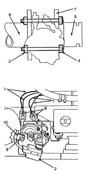
Apply gasket eliminator (item 14, Appendix E) to the
tank to suction pipe flange (6) and the tank outlet
pipe flange (5).
(4)
Separate the two flanges (5 and 6) to allow the tank
valve assembly (7) to be installed without disturbing
the gasket eliminator.
(5)
Insert the tank valve assembly (7) between the two
flanges (5 and 6) Make sure the flow arrow on the
body points away from the tank.
(6)
Apply threadlock liquid (item 29, Appendix E) to all
four capscrews (4).
(7)
Install the capscrews (4) and new locknuts (3) and
tighten to 150 ft lb (203 Nm).
(8)
Install the wiring to the microswitch (2).
(9)
Install the microswitch wiring support clamp (10)
using the micro switch mounting bracket screw (8).
(10)
Install and tighten the air lines (1) into their proper
location on shuttle valves (9) as shown.
(11)
Wipe off excess gasket eliminator from pipe flanges
(5 and 6).
(12)
Allow gasket eliminator to cure for at least one hour
prior to testing for leaks.
(13)
Replace heat shields (see para. 4-11.3).
(14)
Be sure valve operates. Operate from cab (MODE
switch set to CFR) and from structural control panel
(MODE switch set to STRUCT). Tighten/remake
connections as required.
(15)
Be sure cab lamp illuminates when valve is open.
Adjust microswitch as required.
4-229
|