|
| |
TM 5-4210-220-12
4-13 PUMP BODY - Continued
(2)
Inspect insert fasteners in console. Damaged or loose fasteners must be replaced. Notify Direct Support
Level for repair.
(3)
Inspect valve control levers and control rod linkages. If any are bent or have seized ends, repair as
detailed under Valve Lever Repair and Tie Rod Linkage. Repair following.
INSTALLATION
(1)
Place structural control panel on console and support it so that the underside of the panel is accessible.
(2)
Connect all wires to electrical gages and switches. Be sure they are connected as noted under REMOVAL
step 5.
(3)
Connect hoses to air controls and water gages. Be sure they are connected as noted under REMOVAL
step 6.
(4)
Connect throttle and stop control cables to APU (see Winterization System Controls Repair following).
(5)
Apply a 1/8 in. (3 mm) bead of sealant (item 25, Appendix E) to mating surface of console.
(6)
Install control panel and tighten screws (2) firmly.
(7)
Screw control rods (1) into lever boss until rod just bears on shaft. Install spring pin (4).
(8)
Be sure that when rod is rotated clockwise, rod locks to shaft. When rotated fully anticlockwise, rod is free
from shaft and valve operates smoothly.
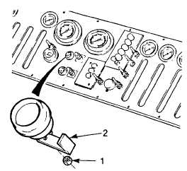
REPAIR
a.
Electric Gage Repair (Tachometer, engine oil pressure, and water temperature gages)
NOTE
Control panel may remain installed. Gages are non-repairable and must be replaced if faulty.
(1)
Tag and remove wires from gage.
(2)
Remove nuts (1) and clamp (2) Remove gage from control panel and discard.
(3)
Install new gage using clamp (2) and nuts (1) provided with the new gage.
(4)
Connect wires to gage as tagged.
(5)
Set battery switch to BOTH and start engine. Check function of new gage. If the engine temperature gage
is replaced, keep the engine running for at least five minutes to allow the cooling system to heat up.
4-121
|