 |
|||
|
|
|||
|
|
|||
| ||||||||||
|
|
 mounted on each side of the front of the radiator furnish
illumination for the engine. Two motor solenoid relays
and motors. one mounted on each hose reel assembly
and one motor solenoid and motor mounted on the
priming pump serve to furnish power for the priming
pump and hose reels. There are two battery charging
receptacles located at the rear of the unit above the
apron. The temperature and oil pressure sending units
are mounted on the engine.
Refer to TM 9-2320-235-10 for the chassis and engine
electrical components.
80. Wiring
a. General. When testing, repairing, or replacing
the wiring, refer to wiring diagram (fig. 3).
b. Testing.
Test a wire for continuity by
disconnecting each end from the component or
components to which it is connected. Touch the test
probes of a multimeter to each end of the wire. If
continuity is not indicated, the wire is defective and must
be repaired or replaced.
c. Repair. Shave the insulation on the wire at both
ends of the break and twist the bare wires together and
solder the connection. Cover the repaired breaks with
electrical tape and friction tape.
If a terminal breaks off a wire, replace it, using a like
terminal.
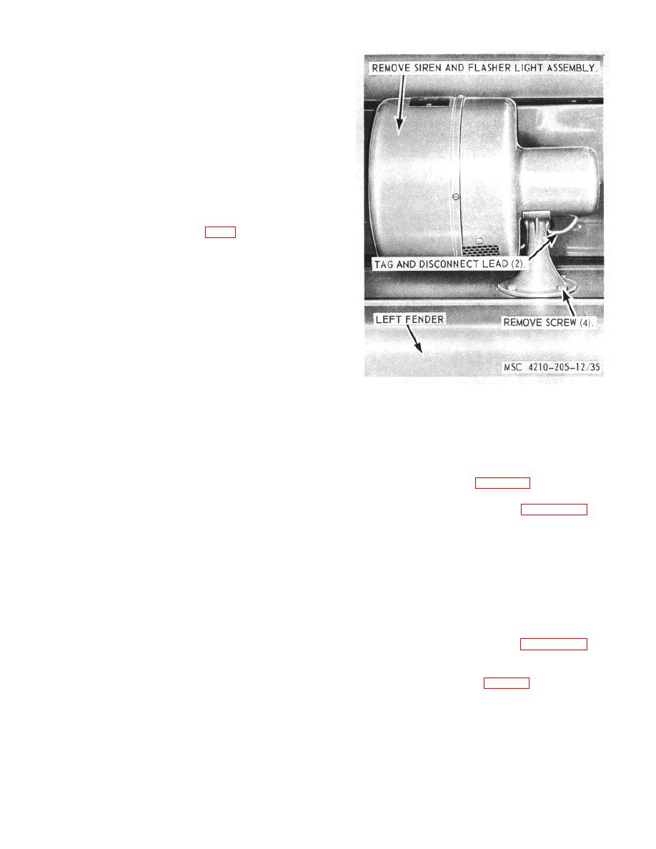
Figure 35. Siren and flasher light, removal and
d. Replacement. Replace a wire by disconnecting
installation.
it from the component or components and remove the
wire. Install a new wire and connect it. If a broken wire
c. Installation. Refer to figure 34, and install the
is part of a wiring harness, disconnect the wire and tape
front directional lights on the fire truck fenders.
the ends. Install a new wire and attach it to the outside
of the wiring harness.
82. Siren and Flasher Light
81. Front Directional Light Assembly
siren and flasher light from the fire truck fender.
a. Removal. Refer to figure 34, and remove the
b. Disassembly.
Refer to figure 36.
and
front directional light assembly from the fire truck
disassemble the siren and flasher light.
fenders.
c. Cleaning, Inspection., and Repair.
b. Cleaning, Inspection, and Repair.
(1) Clean all parts with a clean cloth
(1) Clean all parts with a clean cloth
dampened in an approved cleaning
dampened in an approved cleaning
solvent, and dry thoroughly.
solvent, and dry thoroughly.
(2) Inspect all parts for damaged or defective
(2) Inspect lens, gasket for damaged or
condition.
defective condition.
(3) Replace or repair damaged or defective
(3) Inspect lamp for cracks, breaks, or burned
parts as necessary.
out condition.
d. Reassembly.
Refer to figure 36.
and
(4) Replace or repair damage(d or defective
reassemble the siren and flasher light in the reverse
parts as necessary.
order.
c. Installation. Refer to figure 3.5, an(i install the
siren and flasher light on the fire truck fender.
TAGO 6839A
60
|
|
Privacy Statement - Press Release - Copyright Information. - Contact Us |
