 |
|||
|
|
|||
|
Page Title:
Figure 71.37. Fuel pump assembly. |
|
||
| ||||||||||
|
|
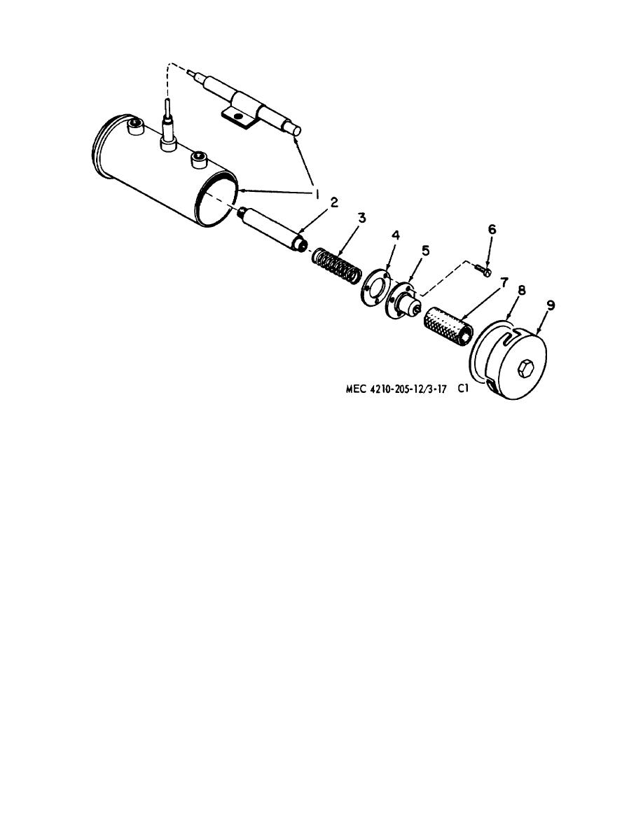 1
Pump assembly
4
Gasket
7
Screen
2
Plunger
5
Cup
8
Gasket
3
Spring
6
Screw
9
Cover assembly
Figure 71.37. Fuel pump assembly.
assemble the plunger assembly or the
(2) If the pump does not operate satisfactorily,
pump assembly.
disassemble, and inspect the screen (7) for
c. Cleaning and Inspection.
clogging. If the screen is clean and the
pump does not operate satisfactorily,
(1) Immerse the screen (7) and the cover (9) in
replace the pump assembly.
cleaning solvent; flush carefully.
b. Fuel Pump Disassembly.
(2) Clean dirt and dust particles from other
(1) Give the cover (9) one-quarter turn
pump parts, using dry, compressed air,
counterclockwise, using a wrench on the cover nut to
carefully applied.
(3) Check the screen (7) for distortion and
remove it from the bottom of the pump. Carefully
damage.
remove the screen (7).
(4) Check all the parts for cracks, distortion,
(2) If further pump disassembly is required,
remove screws (6); lift out the cup (5), gasket (4), spring
signs of overheating, and damaged threads.
(8), and the plunger assembly (2). Do not dis
d. Fuel Pump Reassembly.
(1) Insert the plunger assembly (2) in the pump
assembly (1). Check the fit
AGO 5667A
41
|
|
Privacy Statement - Press Release - Copyright Information. - Contact Us |
