 |
|||
|
|
|||
|
Page Title:
Figure 71.23. Flame switch removal and installation |
|
||
| ||||||||||
|
|
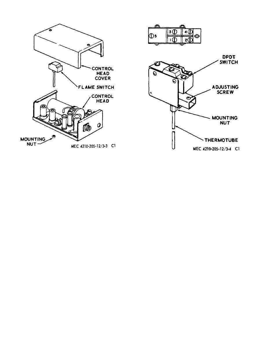 Figure 71.23. Flame switch removal and
Figure 71.24. Flame switch adjustment.
installation.
plate (13). Fasten in place with the
c.
Indicator Lamp.
external mounting nut and install the
(1) To replace the indicator lamp (22, fig.
button.
71.22), remove the lamp button from the
(4) Fasten the receptacle to the angle bracket
light socket (6); then remove lamp (22).
(21) with the mounting screws, washers,
(2) Replace the lamp socket or the
and nuts (1, 2 and 20). Connect the wires
receptacle, remove both as an assembly
according to the wiring diagram (fig.
(2.3). Disconnect the wires leading to the
71.7). The ground wire from the lamp
control switch, circuit breaker, and
connects to a receptacle mounting nut.
ground. To remove the connector (5),
remove the screws (1), washers (2), and
187. Flame Switch, Liquid and Space Heaters
nuts (20) fastening the connector to the
(fig. 71.23).
angle bracket (21). Remove the light
socket (6) by removing the lamp button
a. Removal. Remove the control head (para 192)
and external mounting nut. Inspect the
and remove control head cover. Disconnect the wires
indicator light socket and receptacle for
from the terminals of the flame switch. Unscrew the
broken leads, damaged terminals, and
flame switch mounting nut and remove the flame switch.
worn or damaged threads. If any parts
b. Flame Switch Adjustment (fig. 71.24).
are faulty, replace the entire assembly.
(1) The adjusting screw is a spring-loaded
(3) To install the connector and light
screw at the open end of the switch
assembly (23), insert the light socket
frame.
It adjusts the travel of the
through the hole in the panel (18) and
actuating pin of the switch.
AGO 5667A
23
|
|
Privacy Statement - Press Release - Copyright Information. - Contact Us |
