 |
|||
|
|
|||
|
Page Title:
Figure 71.22. Heater control box assembly. |
|
||
| ||||||||||
|
|
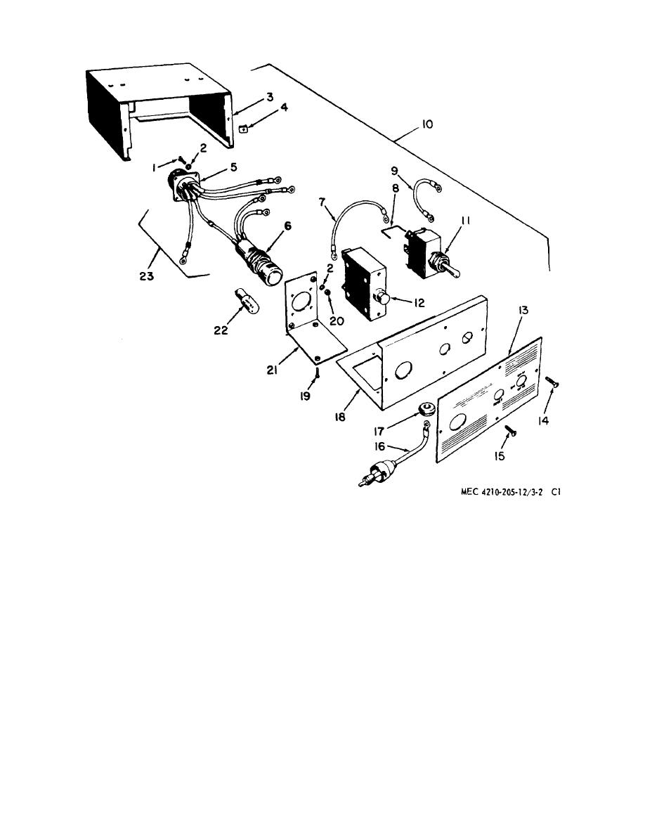 1
Screw
9
Lead
17
Grommet
2
Washer
10
Distribution box
18
Panel
3
Box
11
Switch
19
Screw
4
Nut
12
Circuit breaker
20
Nut
5
Connector
13
Plate
21
Bracket
6
Light
14
Screw
22
Lamp
7
Lead
15
Screw
28
Connector and
8
Wire
16
Lead
light assembly
Figure 71.22. Heater control box assembly.
control switch (11, fig. 71.22) from panel
(3) To install the control switch (11), position
(18).
on the panel and secure with the
mounting nut. (Make certain the switch
lever correctly indicates "ON-HI, OFF,
(2) Check switch continuity with an ohmmeter
ON-LO" operation on the plate.) Connect
in all positions. Make sure the switch
the leads according to the wiring diagram
operates freely. Replace if faulty.
(fig. 71.7.)
AGO 5667A
22
|
|
Privacy Statement - Press Release - Copyright Information. - Contact Us |
