|
| |
TM 9-254
4-2.
Use of Gages.
a.
General. This section contains general information about micrometers and feeler gages. A more detailed
explanation concerning use and operation of these and other types of gages is contained in TM 9-243, Use and Care of
Handtools and Measuring Tools.
b.
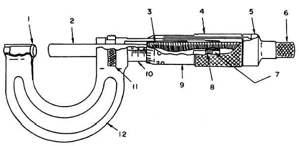
Micrometer (fig. 4-7). Micrometers are used for measurements requiring precise accuracy. The micrometer
screw (3) has a pitch of 40 threads to the inch; in other words, if a screw is turned forty times, it moves the spindle (2)
exactly 1 inch either towards or away from the anvil (1). A clockwise turn moves the spindle toward the anvil. A
counterclockwise turn moves the spindle away from the anvil or opens the micrometer.
(1)
The revolution line along the barrel (10) illustrated in (fig. 4-8), is 1 inch long and is divided into ten equal
parts, indicated by numbered graduations. The unnumbered graduations in turn divide each numbered
graduation into four equal parts.
(2)
Assume that the thimble is turned counterclockwise from completely closed position until the first
numbered graduation is reached. The thimble will have turned four full revolutions and moved a
distance of 0.100 inch (1/10 inch). Each unnumbered graduation is 0.025 of an inch along the revolution
line. Each complete revolution of the thimble moves it this distance.
KEY to figure 4-7:
1.
Anvil
7.
Adjustment nut
2.
Spindle
8.
Slotted nut
3.
Micrometer screw
9.
Thimble
4.
Thimble sleeve
10.
Barrel
5.
Thimble cap
11.
Clamp ring
6.
Ratchet stop
12.
Frame
Figure 4-7. Micrometer Caliper - Cutaway View
4-7
|