|
| |
TM 9-254
8-5.
Oscilloscope Familiarization - Continued
(5)
Set VOLTS/DIV switch (2, fig. 8-9) for a display that remains within the vertical area of screen.
(6)
Adjust POSITION knob (8, fig. 8-9) for desired vertical position of display.
(7)
Adjust POSITION knob (13, fig. 8-10) for desired horizontal position of display.
(8)
Release BEAM FIND switch (4, fig. 8-8).
(9)
If necessary, adjust LEVEL knob (15, fig. 8-10) for a stable display.
(10) Adjust FOCUS knob (2, fig. 8-8) for a well defined display on the screen.
8-6.
Waveform Reading.
a.
General. By analyzing a waveform that is displayed on the oscilloscope CRT, and observing the position of
various control settings, the voltage amplitude, time between pulses, and frequency of the displayed waveform can be
determined.
b.
Measuring Signal Amplitude. Amplitude of a displayed signal is always measured along the vertical axis of
the graduated scale on the face of the CRT.
NOTE
The following steps apply only to measuring the amplitude of signals displayed on the
oscilloscope.
(1)
Perform TURN ON procedures stated in paragraph 8-5f.
(2)
Depress LEFT vertical mode (14, fig. 8-8).
(3)
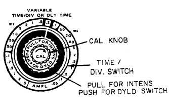
The TIME/DIV OR DLY TIME switch (fig. 8-11) consists of four controls in one. Set the CAL knob fully
clockwise until it clicks. Set the innermost TIME/DIV switch to the .2ms position. Set the PULL FOR
INTENS PUSH FOR DYLD SWITCH to the .2ms position and push in. This means that each horizontal
square will equal .2 milliseconds of time.
Figure 8-11. TIME/DIV or DLY TIME Control
8-17
|

