Order this information in Print

Order this information on CD-ROM

Download in PDF Format


Click here to make tpub.com your Home Page

Page Title: Figure 8-9. Vertical Amplifier Controls
Back | Up | Next

Click here for a printable version

Google


Web
www.tpub.com

Home


Information Categories
.... Administration
Advancement
Aerographer
Automotive
Aviation
Combat
Construction
Diving
Draftsman
Engineering
Electronics
Food and Cooking
Math
Medical
Music
Nuclear Fundamentals
Photography
Religion
USMC
   
Products
  Educational CD-ROM's
Printed Manuals
Downloadable Books


TM 9-254 8-5. Oscilloscope Familiarization - Continued
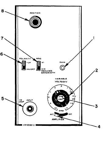
 KEY to figure 8-9: 1. GAIN control 2. VOLTS/DIV (Volts/division) switch 3. CAL (Calibrate) knob 4. AC GND DC (Input coupling) switch 5. INPUT connector 6. POLARITY switch 7. MAG (Magnification) switch 8. POSITION knob Figure 8-9.  Vertical Amplifier Controls (1) Set POSITION knob (8) to midrange.  This control allows for vertical movement of displayed waveform. (2) Set POLARITY switch (6) to the + UP position. (3) Set MAG switch (7) to the X1 position. (4) Turn VOLTS/DIV switch (2) to the .5 position. (5) Turn CAL (RED KNOB) (3) fully clockwise until it clicks in place. (6) Set input coupling switch (4) to the AC position. 8-14

Privacy Statement - Press Release - Copyright Information. - Contact Us - Support Integrated Publishing

Integrated Publishing, Inc. - A (SDVOSB) Service Disabled Veteran Owned Small Business