|
| |
TM 9-254
8-3.
Multimeter Familiarization - Continued
NOTE
For the purpose of the discussion in this section, reference is
made to a Simpson 260 series multimeter.
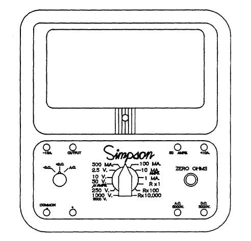
Figure 8-5. Simpson 260 Series - Multimeter
e.
Circuit Jacks (fig. 8-5). There are eight jacks, two in each corner of the front panel. These are the connection
points for the test leads. At the lower left corner are the COMMON - and + jacks. The black lead is connected to the
COMMON - for all circuits and ranges except 10 amperes DC. The red test lead is connected to the + jack for all circuits
and ranges except those designated by other jacks. Across the top of the panel are jacks marked -10A, OUTPUT,
50mAMP, and +10A. For all audio frequency output voltage ranges, use the red test lead connected to the OUTPUT jack.
For the 50 microampere or 250 millivolt DC range, use the red test lead connected to the 50AMP jack. For the 10 ampere
DC range, use the black test lead in the -10A jack and the red test lead in the +10A jack.
8-9
|

