|
| |
TM 9-254
7-10.
Logic Component Schematic Symbols.
a.
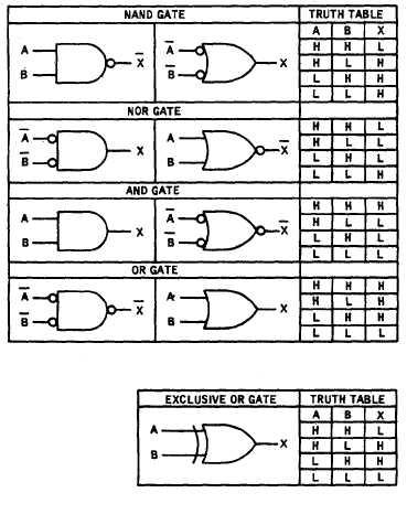
Many systems will contain some amount of digital or logic circuitry. Special logic symbols are used along with
truth tables which describe the logic function performed. Figure 7-19 shows the basic logic gate symbols and their
corresponding truth table. MIL-STD-806 provides a complete reference for approved military logic symbols.
GATE SYMBOLS REPRESENT A SPECIFIC TYPE OF HARDWARE
DESCRIBED BY THE FOLLOWING TRUTH TABLE.
Figure 7-19. Logic Gate Symbols
b.
The logic gates shown in figure 7-19 have only two inputs. In reality these gates may have many inputs
dependent on the loading capacity of the device. Logic gates are normally packaged together in an integrated circuit (IC)
package. These IC’s come in various shapes and sizes. An IC data book will provide the appropriate circuit schematic
and specification for the device.
7-21
|