|
| |
TM 9-254
7-7. Semiconductor Identification - Continued
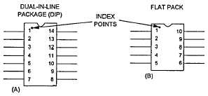
a Flat Pack. Flat Pack integrated circuit packages commonly contain 8,10,12,14, or more leads. Standard center-to-
center lead spacing is 0.050 inch. Unlike DIPs or TO Cans, most flat packs are not mounted through the board, but are
planar mounted to form lap solder joints. The index point may appear on the corner of the first lead or centered between
the number I lead and the top of the component. The leads are numbered counterclockwise from the index point.
Figure 7-16.1. Component Installation
7-8. Military Fuse Identification.
Tables 7-4 thru 7-7 provide various information used in identifying fuses. Figure 7-17 provides an example of a fuse
marking using these tables.
Table 7-4. Fuse Style
Code
Material*
Size (in.)
Code
Material
Size (in)
F01
A
1/4 x 1
F21
C
2.406 x 8-5/8
F02
A
1/4 x 1-1/4
F22
C
2.906 x 10⁻³/8
F03
B
1/4 x 1-1/4
F27
C
13/32 x 3
F04
A
1/4 x 1-1/4
F28
C
13/32 x 4-1/2
F05
A
9/32 x 1-1/4
F29
C
.812 x 5
F06
B
9/32 x 1-1/4
F30
C
.812 x 10
F07
A
13/32 x 1-1/2
F60
D
13/32 x 1-1/2
F09
C
13/32 x 1-1/2
F61
D
.562 x 2
F10
C
13/32 x 1-1/2
F62
D
.812 x 3
F11
B
13/32 x 1-1/2
F63
D
1.312 x 5-7/8
F15
C
9/16 x 2
F64
D
1.875 x 7-1/8
F16
C
.812 x 3
F65
D
2.405 x 8-5/8
F19
C
1.312 x 5-7/8
F66
D
2.906 x 10⁻³/8
F20
C
1.875 x 7-1/8
F67
D
2.000 x 10⁻³/8
*A
Glass
B
Plastic or Ceramic
C
Fiber
D
Glass Melamine
Table 7-5. Fuse Voltage Ratings
Code
Voltage
Code
Voltage
A
31
H
500
B
52
J
1000
C
90
L
2500
D
125
N
5000
G
250
P
10000
7-16 Change 6
|

