|
| |
TM 9-254
7-6 Inductor Identification.
Although not used as much as resistors and capacitors, inductors are used generally in tuning sections of electronic
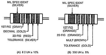
circuits Inductors may be fixed or variable as is the case with resistors and capacitors. Figure 7-12 provides several
examples and indicates the color code used for marking radio frequency (rf) inductors. Variable inductors will usually
have the size and voltage ratings marked on the side of the inductor.
COLOR CODE MARKING FOR MILITARY
STANDARD INDUCTORS
COLOR CODING FOR TABULAR ENCAPSULATED R F. CHOKES AT A, AN EXAMPLE
OF THE CODING FOR AN 8 2 UH CHOKE IS GIVEN AT B. THE COLOR BANDS FOR
A 330 UH INDUCTOR ARE ILLUSTRATED
COLOR CODING FOR TABULAR ENCAPSULATED R F CHOKES
SIGNIFICANT
INDUCTANCE
COLOR
FIGURE
MULTIPLIER
TOLERANCE
(PERCENT)
BLACK
0
1
1
BROWN
1
10
2
RED
2
100
3
ORANGE
3
1,000
YELLOW
4
GREEN
5
BLUE
6
VIOLET
7
GRAY
8
WHITE
9
NONE
20
SILVER
10
GOLD
DECIMAL POINT
5
MULTIPLIER IS THE FACTOR BY WHICH THE TWO COLOR FIGURES
ARE MULTIPLIED TO OBTAIN THE INDUCTANCE VALUE OF THE
CHOKE COIL
Figure 7-12. RF Inductor Identification
7-13
|