|
| |
TM 9-254
6-3.
Use of Pin Boards.
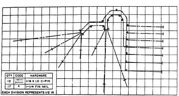
Pin boards are used to shape the wires for binding into a harness. Figure 6-2 shows a typical pin board diagram. The pin
board diagrams of wiring harnesses for fire control equipment appear in the pertinent technical manual. Reference is
made to these diagrams as applicable in the rebuild instructions. Individual wire routing for the boards will be found on the
applicable wiring harness diagram. Cut and stamp marker sleeves to suit from bulk sleeve material.
Figure 6-2. Typical Pin Board Diagram
6-4.
Coding Wires.
Fit marker sleeves on the conductors in such a manner that the identifying characters can easily be read from one
direction when the wiring has been installed in the equipment. In the case of two rows of connections, on opposite sides of
the terminal block, it may be more practical to arrange the sleeves so they may be read from opposite directions. However,
all the sleeves in each individual row should read from a single direction. The position of the sleeve designation will be
shown in the wiring harness diagram referenced in the applicable rebuild instructions
6-2
|