|
| |
TM 9-254
4-12.
Soldering Station-continued
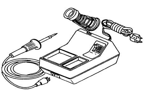
Figure 4-22. Electric Soldering Station
b.
Principles of Operation. The electric soldering iron transmits heat to the tip after the heat is produced by
electric current which flows through a self-contained coil of resistance wire called the heating element (fig. 4-23).
(1)
This type of soldering iron contains a closed loop method of automatically controlling maximum tip
temperature thereby protecting temperature sensitive components.
(2)
The tip (3) is electrically grounded to protect voltage and current sensitive components. Tip sizes range
from one thirty-second of an inch in diameter to fifteen sixty-fourth of an inch in diameter with a choice of
tip temperatures 600, 700, and 800°F.
(3)
The power unit base (7) contains a tray (8) for holding iron tips, a sponge (9) for keeping the tip clean,
and an iron holder (10) for supporting the iron when not in use.
c.
Tinning the Soldering Tip (fig. 4-23). Before any soldering can be accomplished, the tip should be tinned
(coated with solder) to aid in heat transfer and assure good solder flow.
(1)
Select the desired size tip (3) and position tip into barrel nut assembly (4). Secure barrel nut assembly
to the heater (2) and place soldering iron (1) into iron holder (10).
4-26
|

