 |
|||
|
|
|||
|
Page Title:
Azimuth Mechanism 800-mil Steps and Level Travel Inspection - continued |
|
||
| ||||||||||
|
|
 TM 9-1240-375-34&P
0100 00
TEST AND INSPECTION - Continued
Azimuth Mechanism 800-mil Steps and Level Travel Inspection - Continued
NOTE
The following data is required to do steps 10, 11, and 13.
Columns one and two give the required settings, in 800-mil increments, to be used in
steps 10 and 11.
Column three (step 13) gives the reading that should appear on the deflection
counter after doing steps 10 and 11.
Table 1. Azimuth Mechanism Inspection - Settings and Readings.
AZIMUTH
AZIMUTH TEST
DEFLECTION
KNOB SETTING
STAND SETTING
COUNTER READING
(MILS)
(MILS)
(MILS)
4000
5600
4000
4800
0000
4800
5600
0800
5600
0000
1600
0000
0800
2400
0800
1600
3200
1600
2400
4000
2400
3200
4800
3200
NOTE
When doing the next step, be careful not to turn azimuth knob past the specified
counter setting.
4
7
1 fc 6 6 7
10.
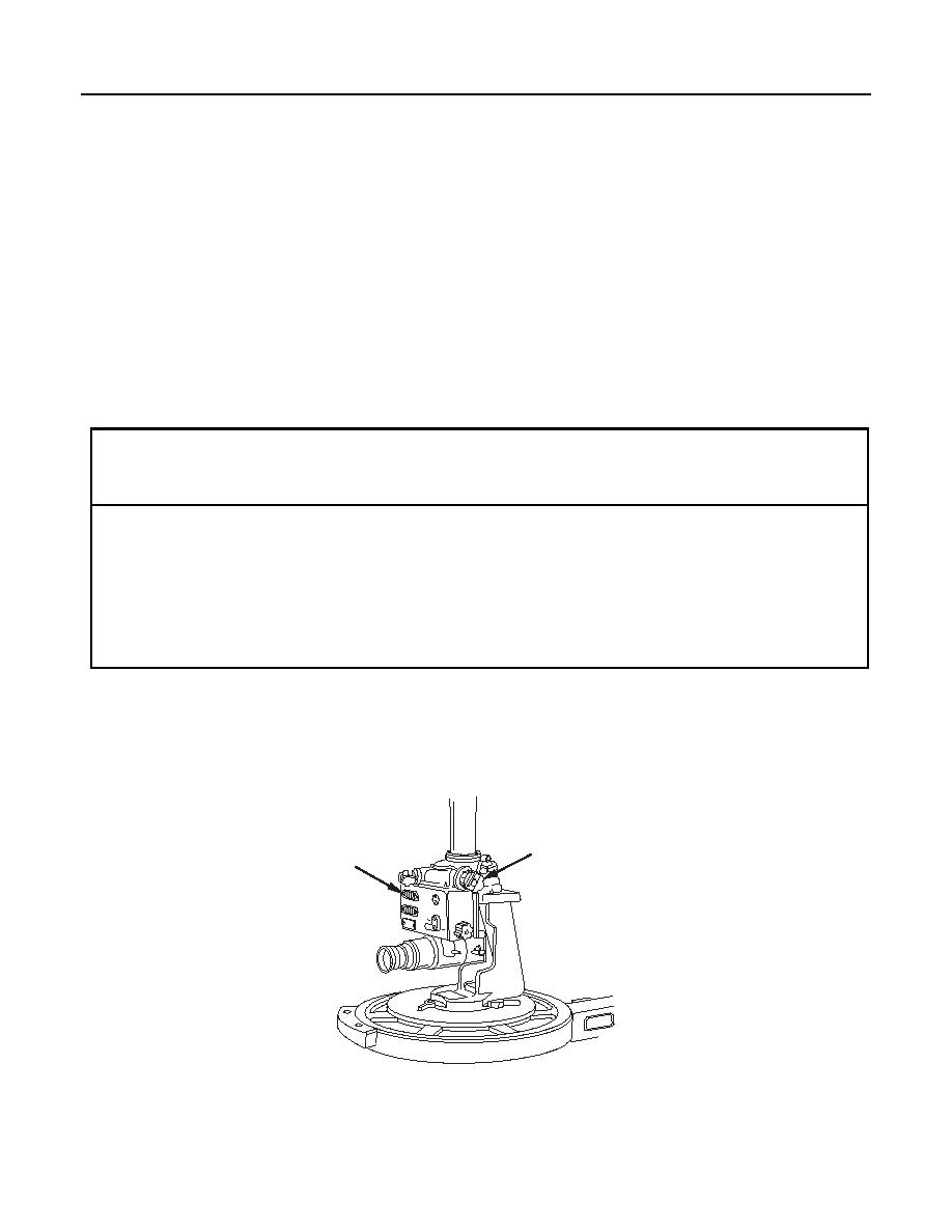
Turn azimuth knob (4) clockwise until azimuth counter (7) is set at 4000 mils.
0100 00-18
|
|
Privacy Statement - Press Release - Copyright Information. - Contact Us |