 |
|||
|
|
|||
|
Page Title:
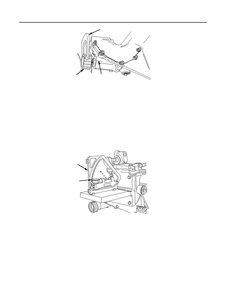
Cross Level Mechanism Backlash Inspection - continued |
|
||
| ||||||||||
|
|
 TM 9-1240-375-34&P
0082 00
6
7
4
5
1 fc 5 4 9
NOTE
An index pointer may be made from 1/16 inch diameter rod with sharp point on end.
The index pointer may be held in place mechanically by a small C-clamp (6).
5.
Place index pointer (7) on the cross level knob (4) directly opposite scribed index line (5).
NOTE
Do not go past scribed index line when turning counterclockwise. Ensure scribed
index line and index pointer are in perfect alignment.
6.
Rotate cross level knob (4) at least 1/2 turn clockwise. Turn counterclockwise until index pointer (7)
aligns with scribed line (5).
1
3
8
1 fc 5 5 0
7.
Check fire control quadrant (1) to ensure that level bubble (3) is centered when index pointer is aligned
with scribed index line. If not centered, use micrometer knob (8) to center.
8.
Take reading from micrometer. If the reading has changed more than 1.5 mils, the backlash is
excessive.
NOTE
Repeat steps 1 through 8 as necessary with readings of 150, 300, and 450 mils set on
fire control quadrant. This backlash procedure will be repeated at 0, 150, 300, and
450 mils in the opposite direction of cant, performed in steps 1 through 8.
0082 00-7
|
|
Privacy Statement - Press Release - Copyright Information. - Contact Us |
