 |
|||
|
|
|||
|
|
|||
| ||||||||||
|
|
 TM 9-1240-375-34&P
0077 00
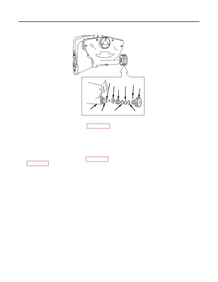
ASSEMBLY
1
10
7
4
9
5
2
6
8
3
1 fc 4 9 8
1.
Apply a light coat of grease (item 16, WP 0152 00) to worm shaft assembly (1) and install in quadrant
support housing (2) ensuring that slot in bearing (3) is aligned with guide pin in quadrant support
housing.
2.
Install spherical plain bearing (4), ensuring that slot is aligned with guide pin in quadrant support
housing (2). Install externally threaded ring (5) on worm shaft assembly (1). Tighten externally
threaded ring.
3.
Apply a light coat of grease (item 16, WP 0152 00) to flat washer (6), new mechanical felt (7) (item 7,
NOTE
Perform steps 4 and 5, and continue with step 7, if new worm shaft assembly has
been installed. Perform step 6 if previously-installed components are used.
4.
Install knob (9) on worm shaft assembly (1) and secure with setscrew, NSN 5305-00-655-9246. Using
the pilot hole located on the knob, drill hole through worm shaft assembly.
5.
Remove setscrew from knob (9).
6.
Align reference marks and install knob (9) on worm shaft assembly (1).
CAUTION
Support cross level knob in V block on solid surface to prevent damage to worm shaft.
7.
Install headless straight pin (10).
0077 00-6
|
|
Privacy Statement - Press Release - Copyright Information. - Contact Us |
