 |
|||
|
|
|||
|
|
|||
| ||||||||||
|
|
 TM 9-1240-375-34&P
0054 00
ASSEMBLY - Continued
21
20
14
15
1 fc 2 0 6
NOTE
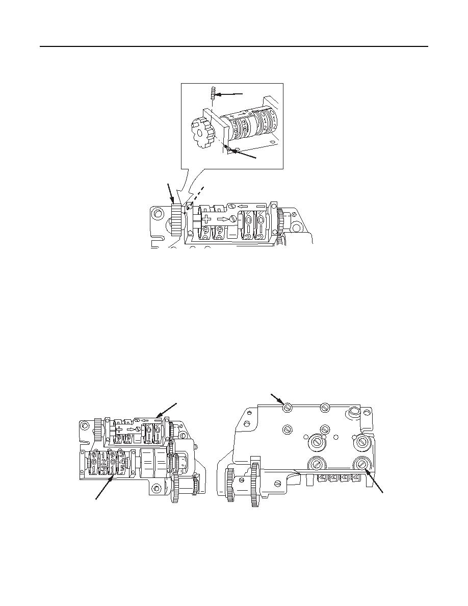
Perform step 14 only if correction counter or counter detent has been replaced.
14.
Install and tighten screw (20) (No. 2X56) in counter detent (14). Drill and ream 0.0625 in. diameter
hole through counter detent and counter shaft (15).
CAUTION
Support counter detent in V block on solid surface to prevent damage to shaft.
15.
Install headless straight pin (21) and remove screw (20), if present.
19
12
9
6
1 fc 2 0 7
1 fc 2 0 8
Top View
Bottom View
16.
Check elevation counter (6) and correction counter (12) for smooth rotation. If movement is not
smooth, loosen four machine screws (9) and four machine screws (19), and reposition counters.
0054 00-10
|
|
Privacy Statement - Press Release - Copyright Information. - Contact Us |