 |
|||
|
|
|||
|
|
|||
| ||||||||||
|
|
 TM 9-1240-375-34&P
0054 00
DISASSEMBLY
2
1
3
2
1 fc 1 8 8
1
1 fc 1 8 9
Top View
Bottom View
1.
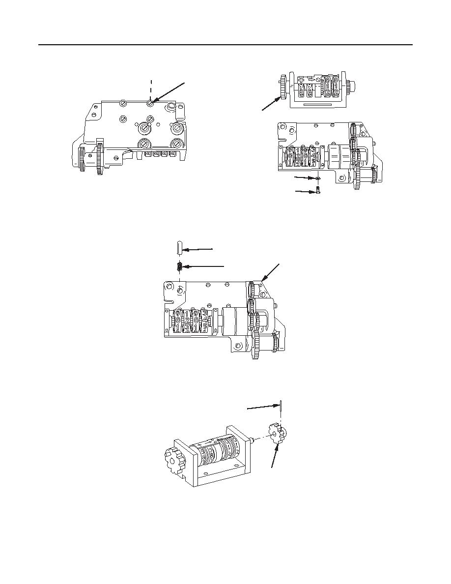
Remove four machine screws (1), four lockwashers (2), and correction counter (3). Discard lockwashers.
4
6
5
1 fc 1 9 0
Top View
2.
Remove detent plunger (4) and compression helical spring (5) from support (6).
7
8
1 fc 1 9 1
CAUTION
Support spur gear in V block on solid surface to prevent damage to shaft.
3.
Remove headless straight pin (7) and spur gear (8).
0054 00-3
|
|
Privacy Statement - Press Release - Copyright Information. - Contact Us |