 |
|||
|
|
|||
|
|
|||
| ||||||||||
|
|
 TM 9-1240-375-34&P
0053 00
CAUTION
Use extreme care when removing cover assembly. A connector on a short wire
harness on cover is connected to a connector on a short wire harness on quadrant.
These connectors and wire harnesses are easily damaged.
3.
Carefully pull cover assembly (3) and O-ring (5) away from housing assembly (6) and disconnect
connector (7) from connector (8). Remove cover assembly and O-ring. Discard O-ring.
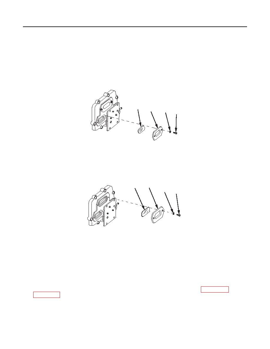
DISASSEMBLY
4
3
2
1
1 fc 1 8 1
M17A1/M18A1 Quadrant
1.
Remove two machine screws (1), two lockwashers (2), window plate (3), and optical instrument window
(4). Discard lockwashers.
7
8
6
5
1 fc 1 8 2
M17A1/M18A1 Quadrant
2.
Remove two machine screws (5), two lockwashers (6), window plate (7), and optical instrument window
(8). Discard lockwashers.
REPAIR OR REPLACEMENT
1.
Replace entire cover assembly if cracked, broken, or damaged in any way that would allow foreign
matter to enter interior of the M17A1/M18A1 quadrant.
2.
Repair by replacing authorized parts that do not meet inspection criteria. Refer to WP 0111 00 and
0053 00-3
|
|
Privacy Statement - Press Release - Copyright Information. - Contact Us |
