 |
|||
|
|
|||
|
|
|||
| ||||||||||
|
|
 TM 9-1240-375-34&P
0050 00
ASSEMBLY - Continued
23
24
1 fc 1 5 1
M17A1/M18A1 Quadrant
21.
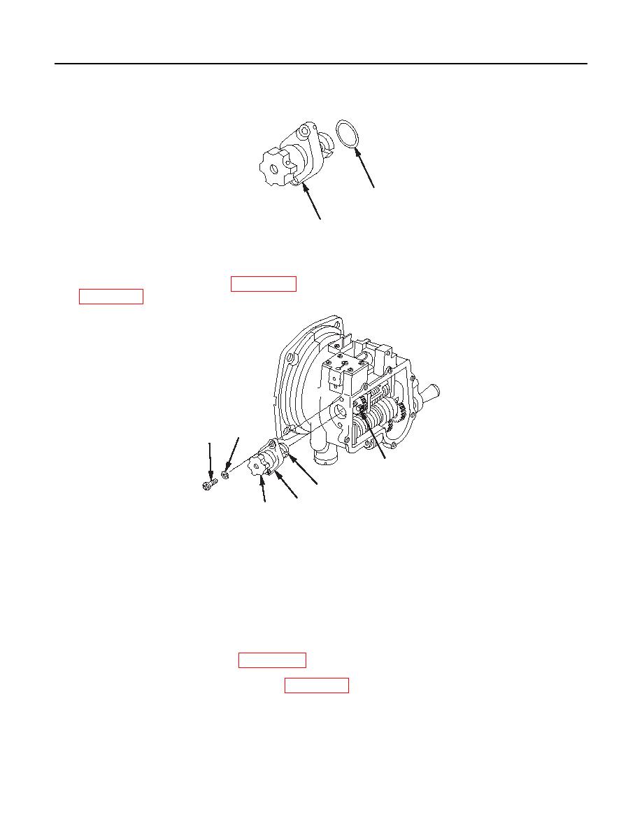
Place new O-ring (23) (item 36, WP 0111 00) on correction knob assembly (24). Apply grease (item 16,
29
28
27
26
24
25
1 fc 1 5 2
M17A1/M18A1 Quadrant
22.
Ensure rotation of knob (25) is smooth through 19-1/4 revolutions.
a.
Turn knob (25) clockwise until it stops.
b.
Then turn counterclockwise 9-1/2 turns.
23.
Install correction knob assembly (24) and align slot (26) with headless straight pin (27).
24.
Apply sealing compound (item 13, WP 0152 00) to threads of two machine screws (28).
25.
Install two new lockwashers (29) (item 18, WP 0111 00) and two machine screws (28).
0050 00-14
|
|
Privacy Statement - Press Release - Copyright Information. - Contact Us |