 |
|||
|
|
|||
|
|
|||
| ||||||||||
|
|
 TM 9-1240-375-34&P
0050 00
3
9
11
10
5
4
1 fc 1 2 8
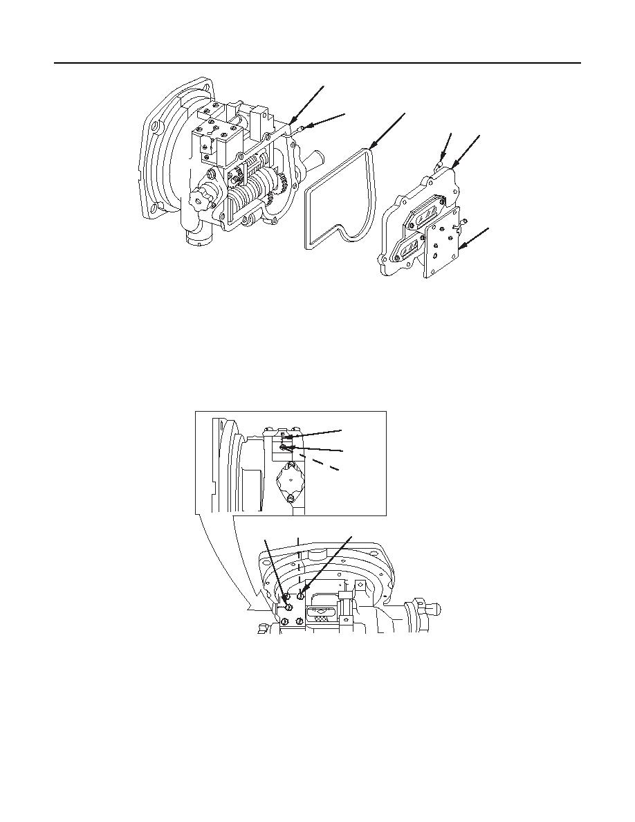
M17A1/M18A1 Quadrant
CAUTION
Use extreme care when removing cover assembly. A connector on a short wire
harness on cover is connected to a connector on a short wire harness on quadrant.
These connectors and wire harnesses are easily damaged.
4.
Carefully pull cover assembly (5) and O-ring (9) away from housing assembly (3) and disconnect
connector (10) from connector (11). Remove cover assembly and O-ring. Discard O-ring.
12
15
16
13
14
17
1 fc 1 2 9
M17A1/M18A1 Quadrant
5.
Remove and discard lock wire (12).
6.
Remove four machine screws (13) and four lockwashers (14). Discard lockwashers.
7.
Loosen setscrew (15) and cushioning pad (16).
8.
Remove machine screw (17).
0050 00-3
|
|
Privacy Statement - Press Release - Copyright Information. - Contact Us |
