 |
|||
|
|
|||
|
Page Title:
M171 Telescope and Quadrant Mount - continued |
|
||
| ||||||||||
|
|
 TM 9-1240-375-34&P
0002 00
LOCATION AND DESCRIPTION OF MAJOR COMPONENTS - Continued
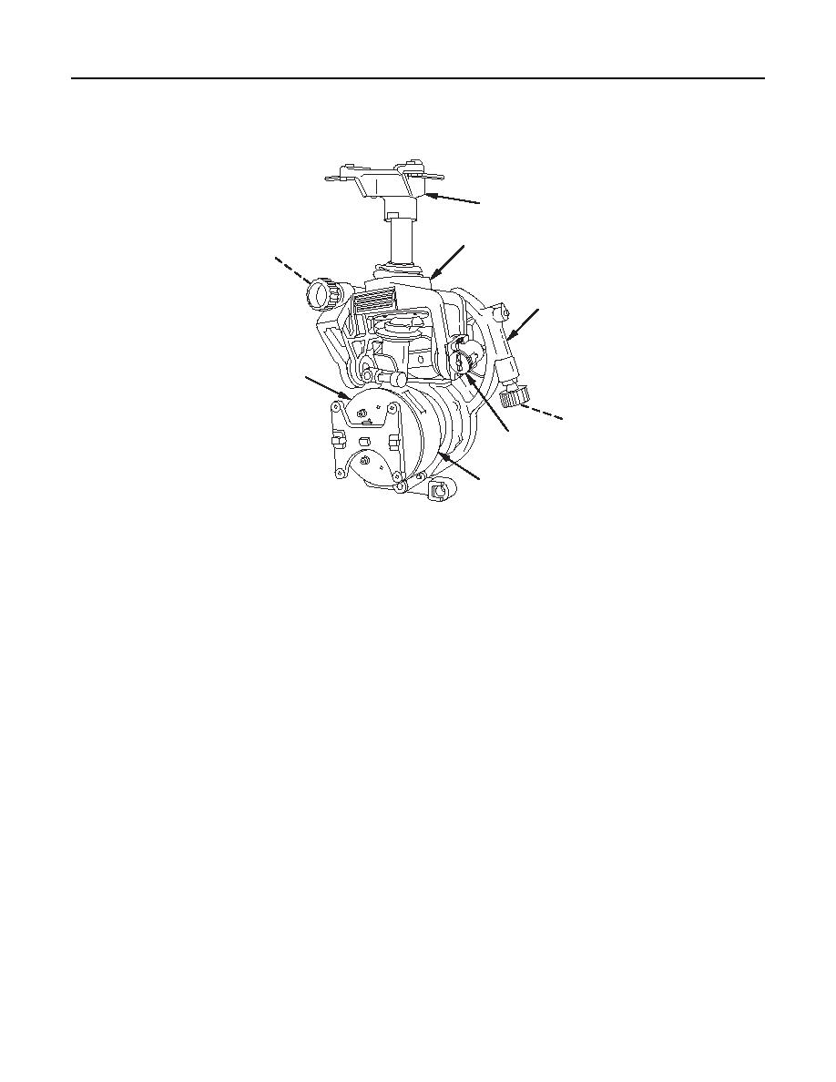
M171A1 Telescope and Quadrant Mount
1
2
3
4
6
5
8
7
M 171A 1
1 fc 0 1 1
1.
Optical Instrument Support (1). The optical instrument support, located at the top of the M171A1
mount, seats the M137/M137A2/M137A3 telescope.
2.
Optical Instrument Rocker Assembly (2). The optical instrument rocker assembly houses the cross-
leveling mechanism. In conjunction with the elevation-leveling mechanism located on the housing
assembly, the optical instrument rocker assembly establishes the vertical axis reference for azimuth
compensation.
3.
Worm Shaft Assembly (Cross Level) (3). The worm shaft assembly is located in the optical instrument
rocker assembly. The worm shaft assembly is actuated by a cross level knob. This assembly controls
the cant of the M171A1 mount.
4.
Housing Assembly (4). The housing assembly houses the elevation-leveling mechanism and supports
the plunger assembly. The plunger assembly secures the M171A1 mount in an upright position on the
weapon. A spring-loaded guide is provided to prevent damage to the M171A1 mount if the elevation
limit of the instrument is exceeded.
5.
Worm Shaft Assembly (Elevation) (5). The worm shaft assembly is located in the housing assembly. It
is actuated by the elevation knob.
6.
Arm and Adapter Assembly (6). The arm and adapter assembly is located on the face of the arm
assembly, and supports the M17A1 quadrant. The mounting adapter provides the keyed interface for
assembling the M171A1 mount to the pre-qualified mounting adapter on the weapon trunnion. This
adapter also houses the bar. It serves as a reference about which the M171A1 mount is adjusted to
compensate in azimuth and elevation for the effects of trunnion cant.
0002 00-8
|
|
Privacy Statement - Press Release - Copyright Information. - Contact Us |
