|
| |
TM 750-116
(d) Perform purging and charging procedure para
2-5.b.
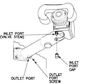
(e) Remove outlet port screw and discard.
(f) Purge instrument at 4 psig for 10 minutes or until
all visible traces of moisture are gone.
(g) Apply thin coat of lubricant (item 3, appx B) to
o-ring of replacement outlet port screw and install.
(h) Torque outlet port screw to 24-28 in-lb (28-32
cm kg).
(i) Charge instrument at 4 psig for 10 minutes.
(j) Leak test instrument for minimum of 10 minutes.
If leak is detected, repair per table 3-1.
Table 3-1 Leak Test, Integrated Sight Unit
Part leak de-
tected from
lamp window
collar assembly
lampholder as-
sembly cover
valve assembly
all other parts of
ISU
Manual re-
ferred for M2,
M3, M2A1, and
M3A1 vehicles
TM9-2350-252-
20-2-3
TM9-2350-252-
20-2-3
TM9-2350-252-
20-2-3
TM9-1425-474-
34-1 (M2/M3)
TM9-1425-453-
34-1 (M2A1/
M3A1)
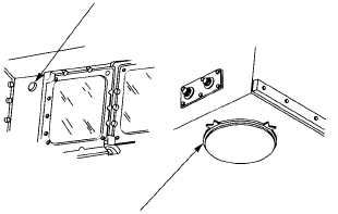
LAMP WINDOW COLLAR ASSEMBLY
Manual re-
ferred for
M2A2 and
M3A2 vehicles
TM9-2350-284-
20-2-3
——
TM9-2350-284-
20-2-3
TM9-1425-453-
34-1
LAMPHOLDER COVER (M2, M3, ONLY)
Figure 3-49 Lamp Assembly
(k) For M2A1, M3A1, M2A2, and M3A2 only, re-
duce pressure from 4 psig to approximately 1.5 psig.
(l) For M2, M3, M2A1, and M3A1 only, close sight
shield assembly per TM 9-2350-252-20-2-3.
(m) For M2A2 and M3A2 only, install ballistic sight
shield assembly per TM 9-2350-284-20-2-3.
(n) Close and secure gunner’s hatch cover per TM
9-2350-252-10-2 (for M2, M3, M2A1, and M3A1 only) or
TM 9-2350-284-10-2 (for M2A2 and M3A2 only).
(3) Commander’s Relay Assembly (figs. 3-50
and 3-51).
Figure 3-50 Commander’s Relay Assembly
Commander’s Relay Assembly seals could
rupture if pressure is too high. Never let low
pressure gage get higher than 4 psig.
(a) Open and secure gunner’s hatch cover per TM
9-2350-252-10-2 (for M2, M3, M2A1, and M3A1 only) or
TM 9-2350-284-10-2 (for M2A2 and M3A2 only).
NOTE
Shim(s) may or may not be present between
night sight cover support and turret.
(b) For M2A2 and M3A2 only, remove two screws,
washers, shim(s), and night sight cover actuator handle/sup-
port.
3-22
|


