 |
|||
|
|
|||
|
Page Title:
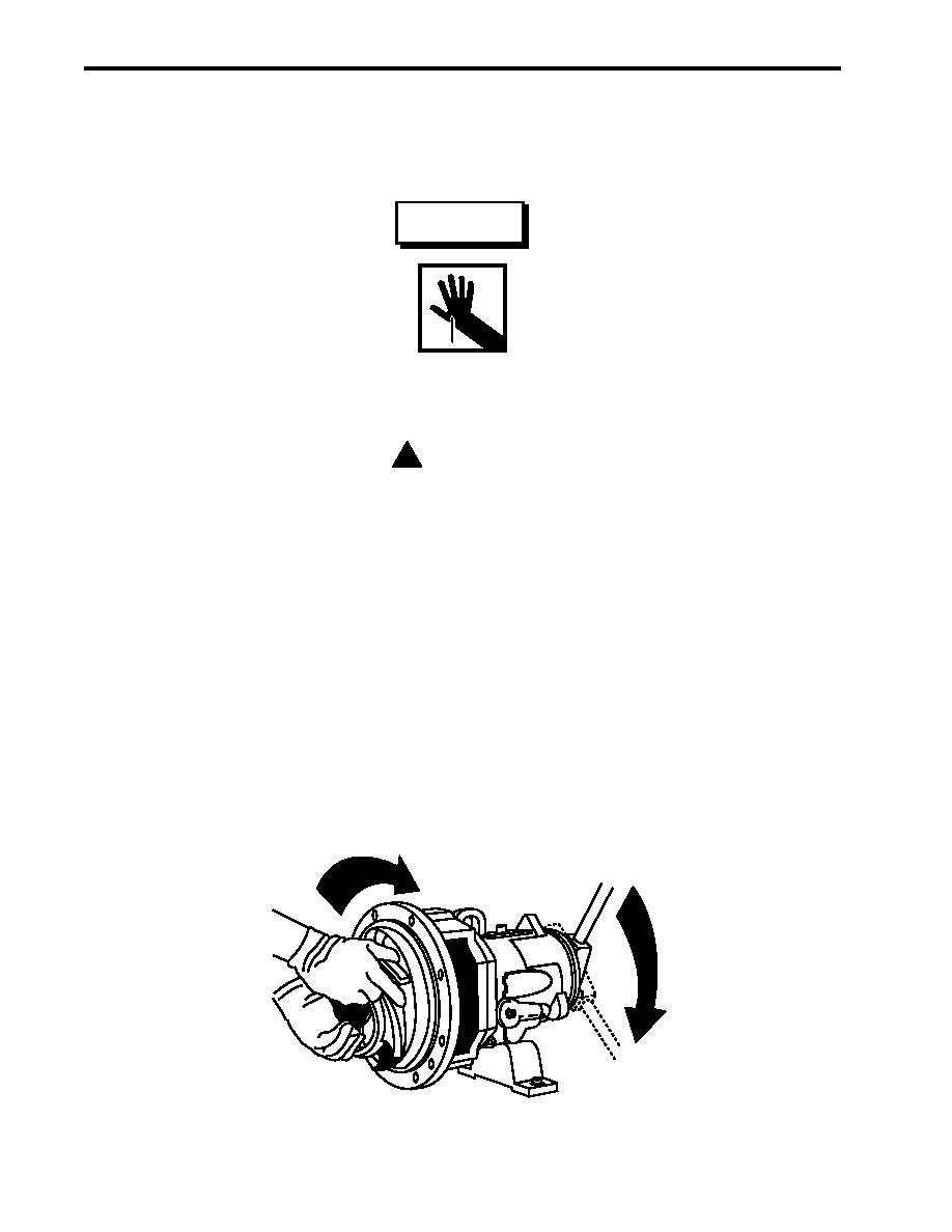
Figure 4. Impeller Installation |
|
||
| ||||||||||
|
|
 TM 55-1925-292-14&P
0037 00
22. Remove the second guide bolt and install the second rear cover cap screw (figure 1, item 18). Tighten the
cap screw to 40 lb-ft (54 Nm).
23. Install the new impeller gasket (figure 1, item 14) onto the shaft (figure 1, item 11).
WARNING
The impeller could have sharp edges. Wear leather gloves to protect hands
when tightening the impeller. Personal injury could result.
! CAUTION
Do not attempt to tighten the impeller on the shaft by hitting the impeller with a hammer
or any other object, or by inserting a pry bar between the impeller vanes. Serious
damage to the impeller may result from such actions.
NOTE
It is recommended that two people install the firefighting pump impeller. The weight of
this type of impeller greatly increases the chance of thread damage and subsequent
lock-up concerns.
24. Install the impeller (figure 1, item 13) on the shaft (figure 1, item 11).
25. Install the impeller wrench from the Durco tool kit on the shaft (figure 1, item 11) at the bearing housing end
and secure it to the shaft by inserting the key in the shaft keyway (figure 1, item 12).
26. With the impeller wrench handle to the left, grab the impeller (figure 1, item 13) with both hands and spin the
impeller forcefully in a clockwise direction to impact the impeller wrench handle on the workbench. Refer to
figure 4.
Figure 4. Impeller Installation
0037 00-8
|
|
Privacy Statement - Press Release - Copyright Information. - Contact Us |
