 |
|||
|
|
|||
|
|
|||
| ||||||||||
|
|
 TM 55-1925-292-14&P
0037 00
WARNING
Do not exceed 25 PSI (1.7 bar) nozzle pressure when using compressed air to dry
parts. Wear goggles for eye protection. Do not direct air stream toward self or
other personnel. Failure to comply with this warning may result in severe per-
sonal injury.
! CAUTION
Do not permit the ball bearings to free spin in the bearing race as the bearing is being
subjected to the compressed air. Bearing failure will result.
3. Use compressed air to remove any debris from the inboard bearing (figure 1, item 24) and outboard bearing
(figure 1, item 31).
ASSEMBLY
1. Install a new inboard oil seal (figure 1, item 35) in the bearing housing adapter (figure 1, item 8).
2. Install a new O-ring (figure 1, item 34) on the bearing housing adapter (figure 1, item 8).
3. Position the bearing housing adapter (figure 1, item 8) on the bearing housing (figure 1, item 5) and secure
it with the four bolts (figure 1, item 33).
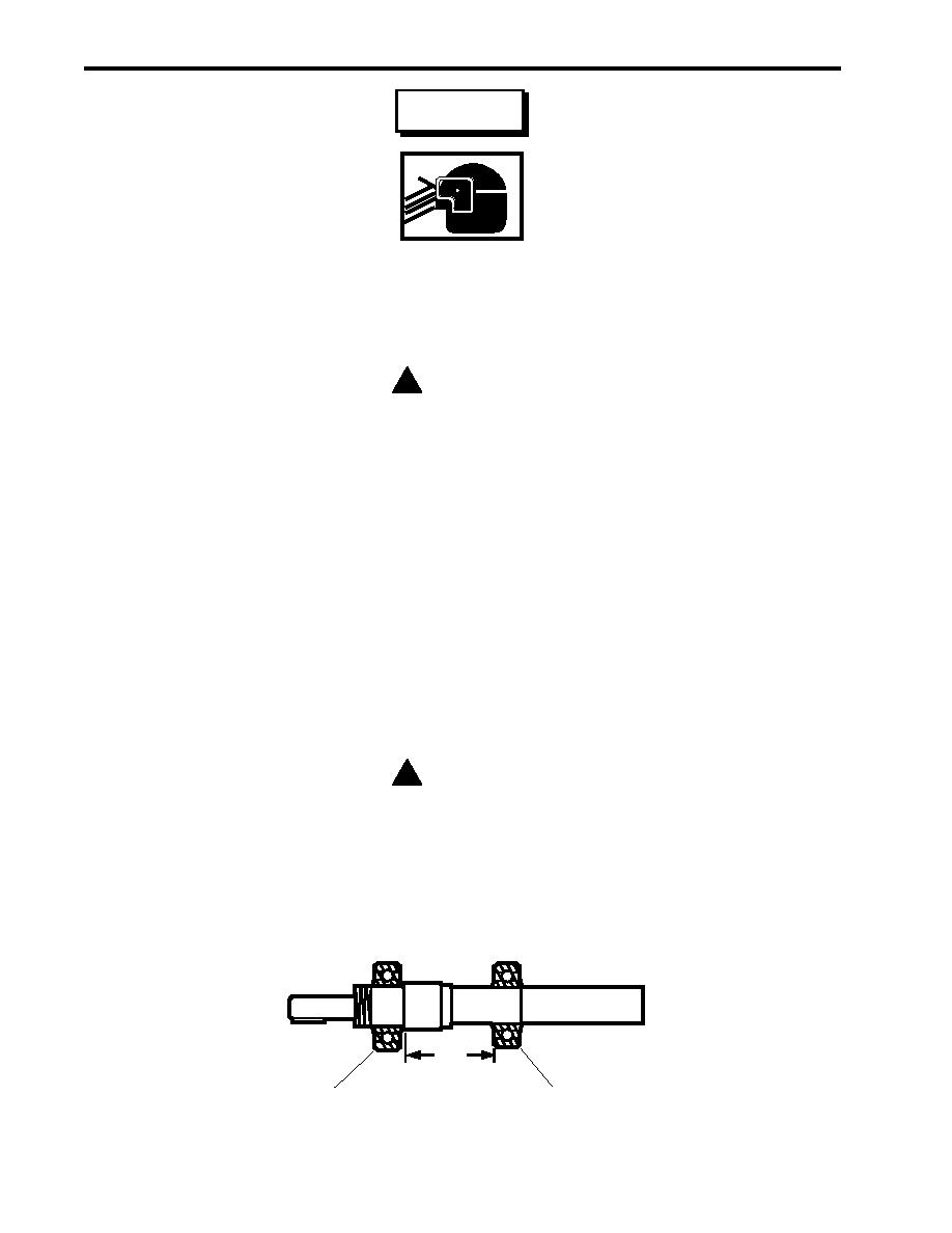
4. Put layout dye onto the shaft (figure 1, item 11) and scribe a line in the layout dye for the location of the
inboard bearing (figure 1, item 24). Refer to figure 3.
! CAUTION
Never apply pressure to the outer race of the bearings as this exerts excess load on the
balls and causes damage to the bearing.
5. Press the inboard bearing (figure 1, item 24) onto the shaft (figure 1, item 11) using an arbor press. Align the
edge of the inner race of the inboard bearing with the scribed line. Lubricate the inboard bearing using
lubricating oil.
5.09"
(129.3 MM)
Inboard Bearing
Outboard Bearing
Figure 3. Bearing Placement
0037 00-6
|
|
Privacy Statement - Press Release - Copyright Information. - Contact Us |