 |
|||
|
|
|||
|
|
|||
| ||||||||||
|
|
 TM 55-1925-292-14&P
0037 00
5. Remove the eight casing nuts (figure 1, item 7) from the bearing housing adapter (figure 1, item 8).
NOTE
Jacking bolt holes may be installed in the bearing housing adapter. If they are present,
install the jacking bolts and use a combination of the jacking bolts and a roller head pry
bar to remove the pump casing.
6. Remove the pump casing (figure 1, item 9) from the bearing housing adapter (figure 1, item 8).
7. Remove the rear cover gasket (figure 1, item 10) from the bearing housing adapter (figure 1, item 8).
8. Install the impeller wrench from the Durco tool kit on the shaft (figure 1, item 11).
9. Secure the impeller wrench to the shaft (figure 1, item 11) by inserting a key in the shaft keyway (figure 1,
item 12).
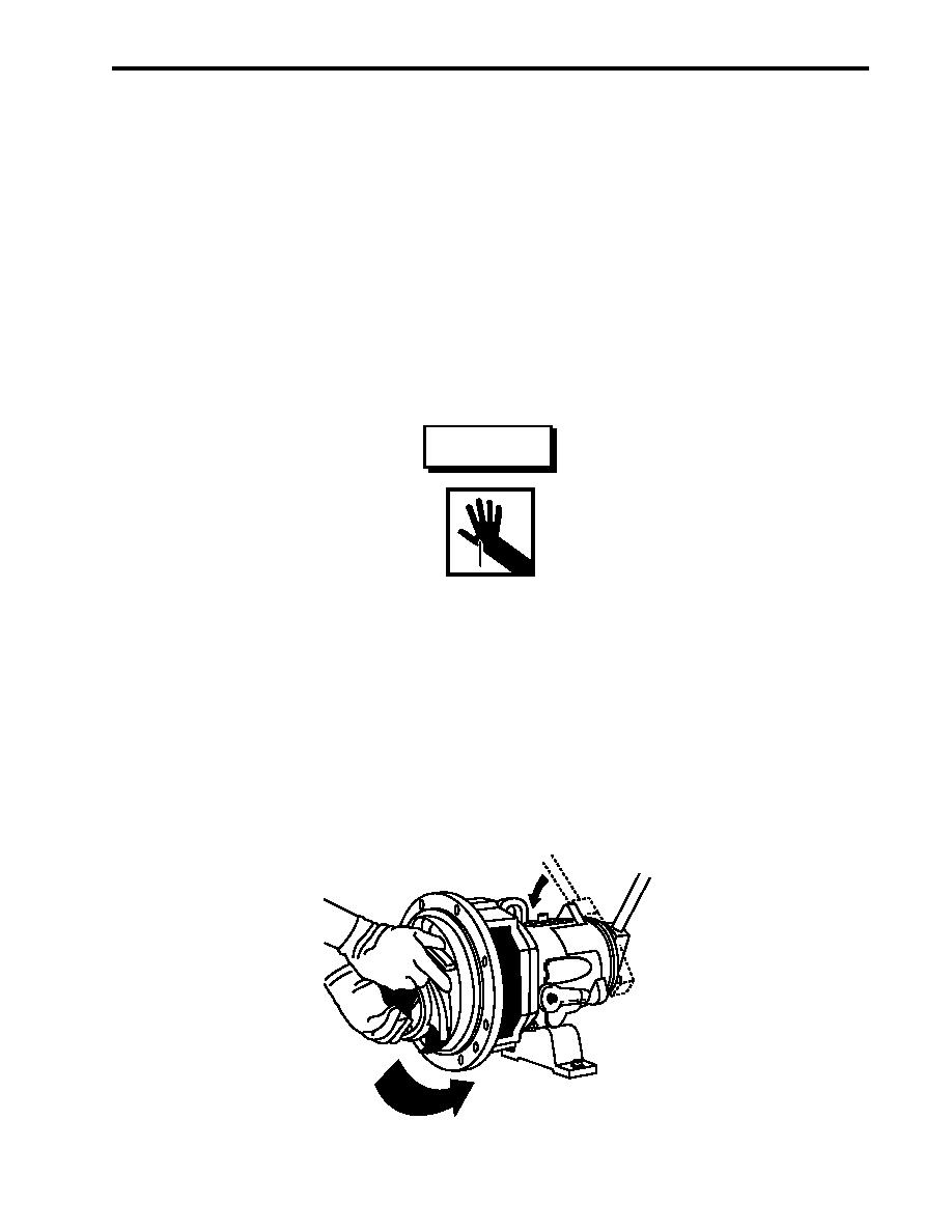
WARNING
The impeller could have sharp edges. Wear leather gloves to protect hands
when removing the impeller. Do not apply heat to the impeller to loosen it from
the shaft. Failure to comply with this warning may result in severe personal
injury or death.
NOTE
It may take several attempts to loosen the impeller using the impeller wrench as de-
scribed below.
10. Turn the impeller (figure 1, item 13) in the clockwise direction and move the impeller wrench in the 11:00
o'clock position. Quickly spin the impeller in the counterclockwise direction causing the impeller wrench to
impact the hard surfaces of the workbench. Refer to figure 2.
Figure 2. Impeller Removal
0037 00-3
|
|
Privacy Statement - Press Release - Copyright Information. - Contact Us |
