 |
|||
|
|
|||
|
Page Title:
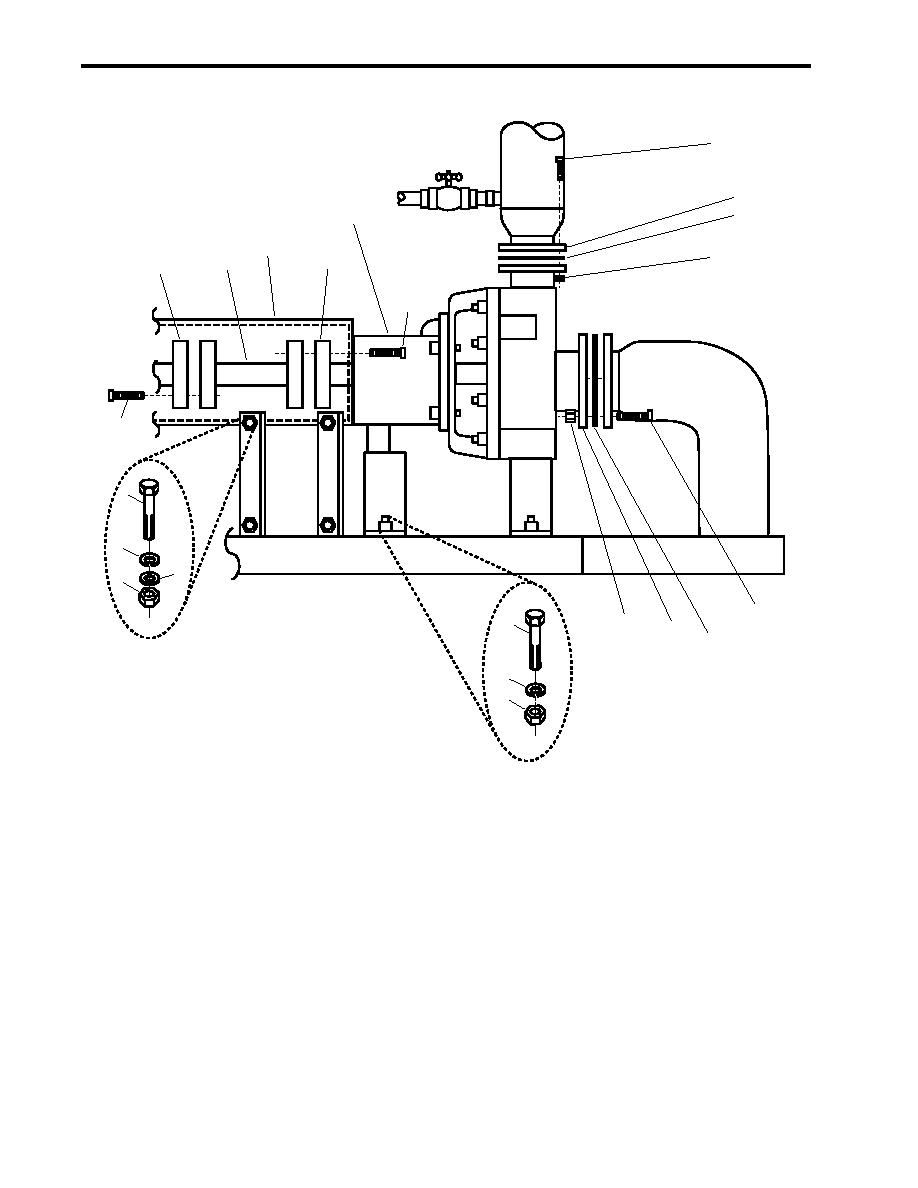
Figure 1. Diesel Engine-Driven Firefighting Pump Removal |
|
||
| ||||||||||
|
|
 TM 55-1925-292-14&P
0036 00
12
13
14
1
6
11
19
16
17
18
15
2
5
4
3
8
7
22
9
10
21
20
Figure 1. Diesel Engine-Driven Firefighting Pump Removal
3. Remove the eight nuts (figure 1, item 7) and eight bolts (figure 1, item 8) that secure the inlet flange (figure 1,
item 9).
4. Remove and discard the gasket (figure 1, item 10).
5. Remove the eight nuts (figure 1, item 11) and eight bolts (figure 1, item 12) that secure the discharge flange
(figure 1, item 13).
6. Remove and discard the gasket (figure 1, item 14).
7. Remove the 12 bolts (figure 1, item 15) that secure the pump drive shaft (figure 1, item 16) to the Power Take-
Off (PTO) output flange (figure 1, item 17).
0036 00-2
|
|
Privacy Statement - Press Release - Copyright Information. - Contact Us |
