 |
|||
|
|
|||
|
Page Title:
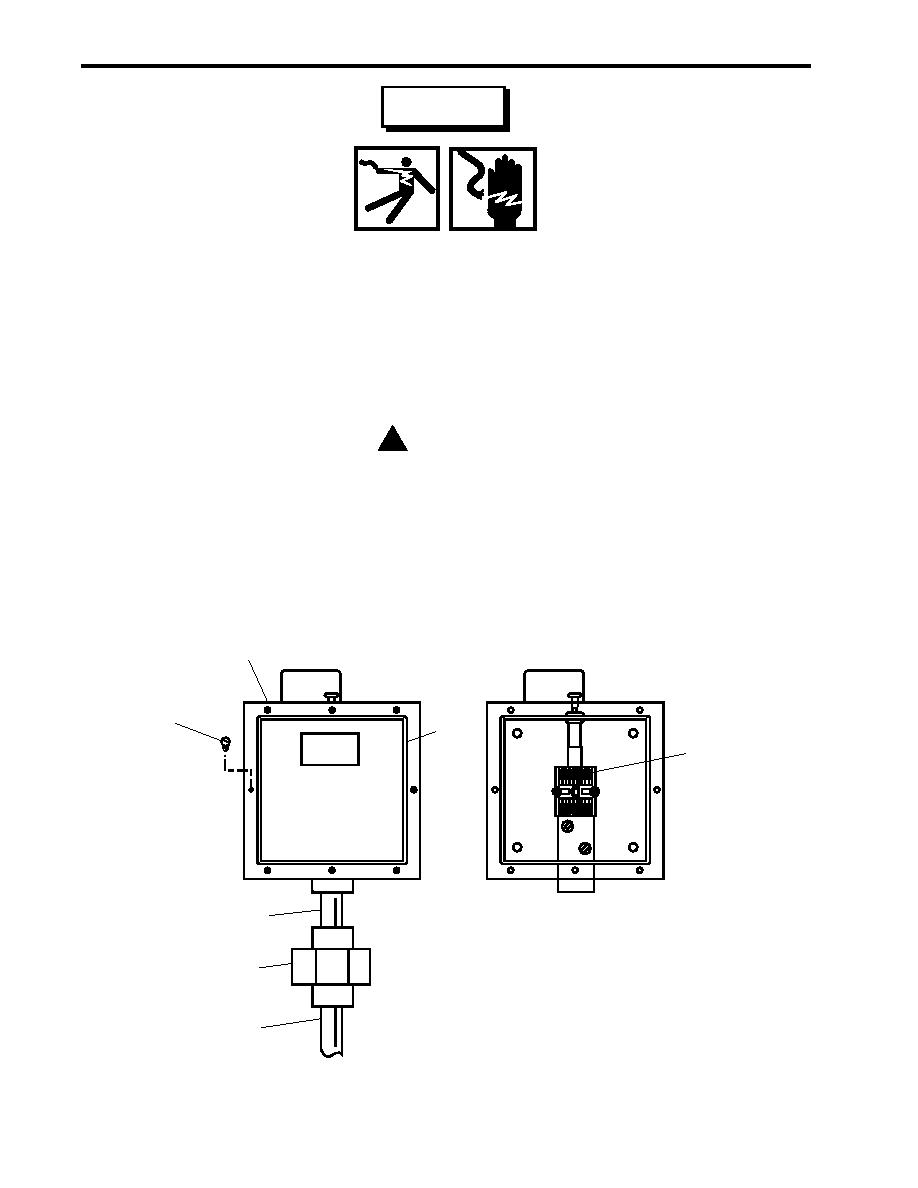
Figure 5. Pressure Operated Switch |
|
||
| ||||||||||
|
|
 TM 55-1925-292-14&P
0032 00
WARNING
Replace or repair components only after the affected circuit has been secured,
locked out and tagged out (FM 55-502). Performing replacement with the circuit
energized may result in injury.
2. Using a multimeter, check for voltage at the terminal board (figure 5, item 4) to ensure that electrical circuits
are deenergized. If voltage is present, ensure that the proper circuit breakers are set to OFF, locked out, and
tagged out (FM 55-502). If no voltage is present, continue with this procedure.
3. Label and disconnect the wiring from the terminal board (figure 5, item 4).
! CAUTION
Never attempt to disconnect union connections with only one wrench. Damage to the
vessel's piping or to the switch's piping could occur. Always use two wrenches.
4. Disconnect the union (figure 5, item 5) at the bottom of the pressure operated switch (figure 5, item 3).
5. Remove the pressure operated switch assembly from the pipe (figure 5, item 6).
Front View
3
OPERATED
OPERATED
SET
SET
1
2
4
7
Front View
(Cover Removed)
5
6
Figure 5. Pressure Operated Switch
0032 00-8
|
|
Privacy Statement - Press Release - Copyright Information. - Contact Us |
