 |
|||
|
|
|||
|
Page Title:
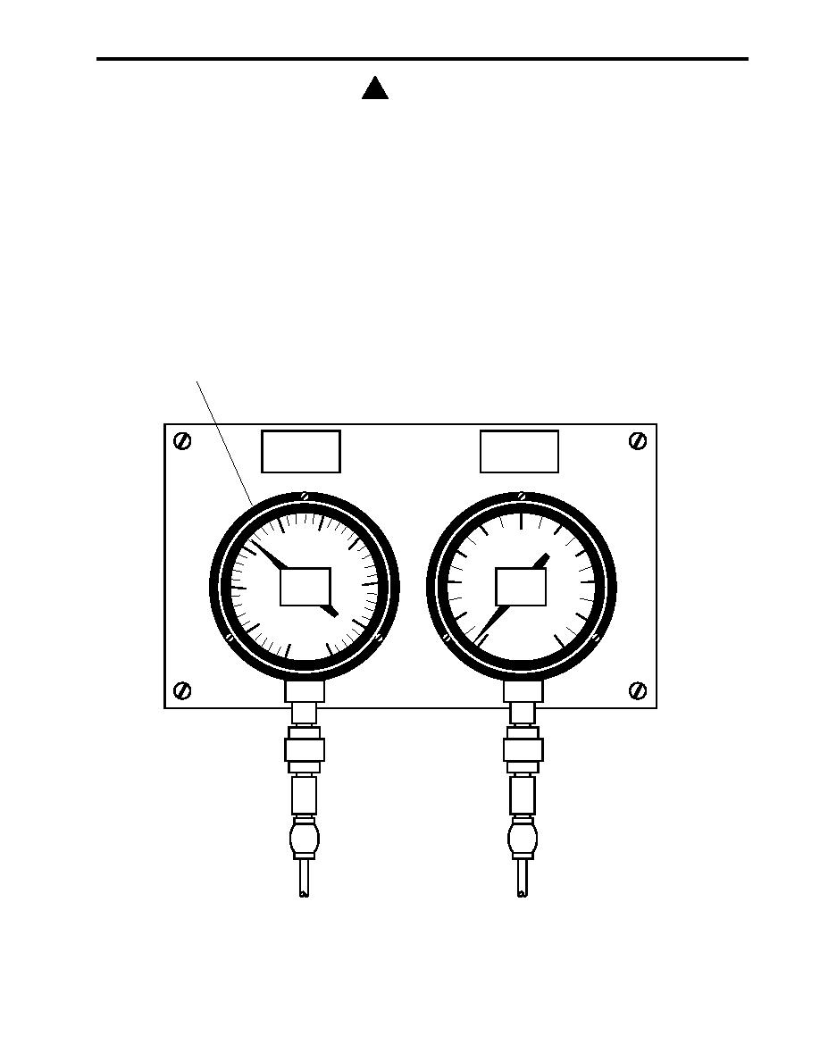
Figure 7. AFFF Discharge Pressure Gauge |
|
||
| ||||||||||
|
|
 TM 55-1925-292-14&P
0029 00
! CAUTION
Do not operate the AFFF pump or the diesel engine-driven fire pump for extended periods
against a dead head. Pump failure could result.
12. Signal the fire monitor operator to CLOSE the monitor discharge valve.
13. With the fire monitor discharge valve CLOSED, observe the AFFF discharge pressure gauge (figure 7, item 1).
14. Observe and record the pressure displayed on the AFFF discharge pressure gauge (figure 7, item 1) when the
relief valve lifts.
15. Instruct the fire monitor operator to OPEN the fire monitor discharge valve.
1
120 150 180
10
5
15
0
210
90
60
240
20
10
270
30
25
20
300
0
30
30
Figure 7. AFFF Discharge Pressure Gauge
0029 00-7
|
|
Privacy Statement - Press Release - Copyright Information. - Contact Us |
