 |
|||
|
|
|||
|
|
|||
| ||||||||||
|
|
 TM 55-1925-292-14&P
0028 00
INSTALLATION
1. Slide the motor coupling flange (figure 3, item 2) onto the motor shaft (figure 3, item 7) with the small end
towards the AFFF pump motor (figure 3, item 3).
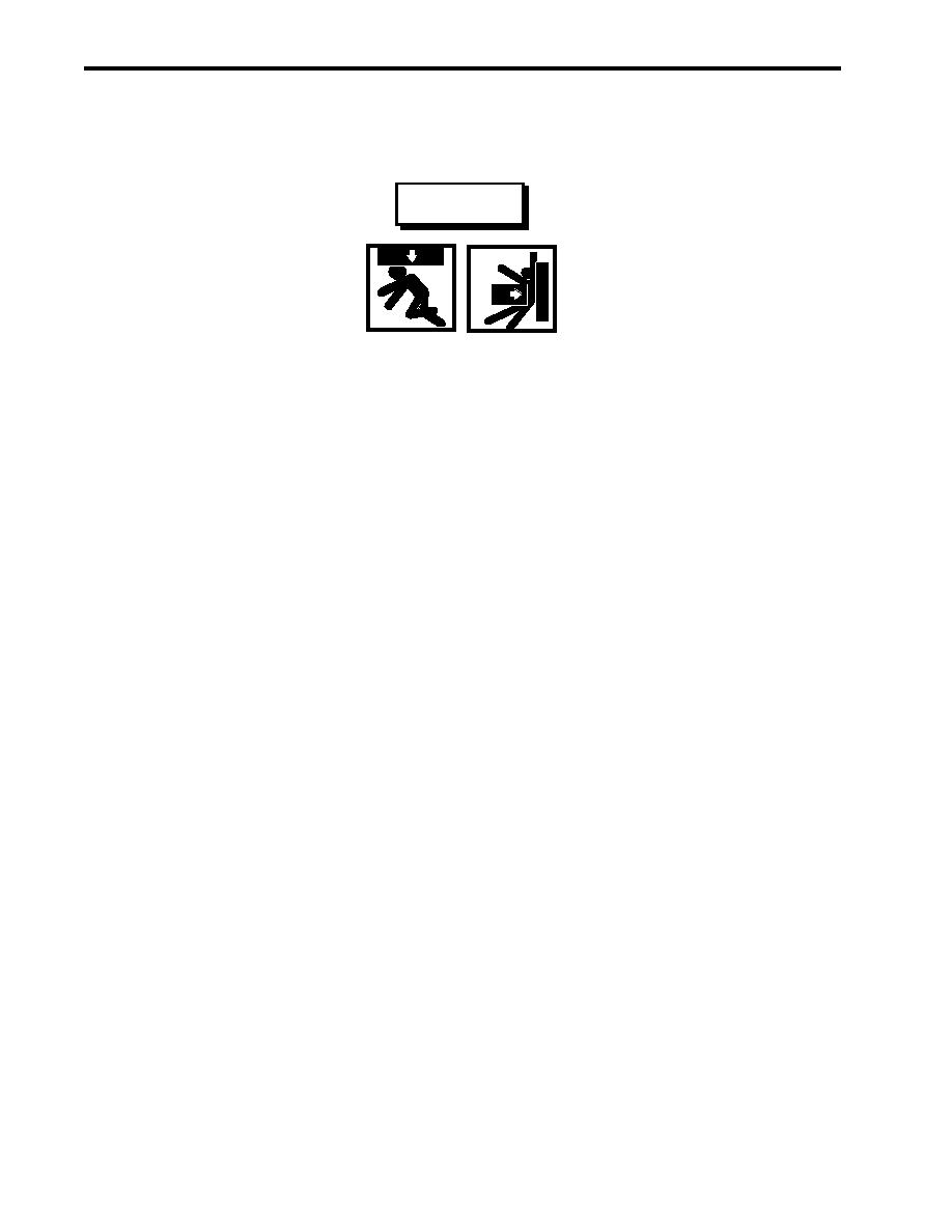
WARNING
Heavy loads can crush. Do not allow any body parts to come under the load or
between the load and a stationary object. Death or serious injury can result.
2. Use a sling and chain hoist to position the AFFF pump motor (figure 3, item 3) on its foundation with the
mounting holes aligned.
3. Install four bolts (figure 3, item 4), four new lockwashers (figure 3, item 5), and four flat washers (figure 3,
item 6). Do not tighten at this time.
4. Align the pump coupling flange (figure 3, item 8) and the motor coupling flange (figure 3, item 2) together
ensuring parallel and angular alignment as shown in figure 4.
NOTE
Correct alignment of the pump coupling and motor coupling is shown in detail A of figure
4. Parallel misalignment and angular misalignment are depicted for reference only in
details B and C, respectively.
5. Once the pump coupling flange (figure 3, item 8) and the motor coupling flange (figure 3, item 2) are correctly
aligned per detail A of figure 4, tighten the motor coupling flange setscrew (figure 3, item 1), and the four bolts
(figure 3, item 4).
NOTE
The coupling alignment may change after tightening the mounting bolts. Always re-
check the coupling alignment following fastener tightening.
6. Check the coupling alignment. If the alignment is not correct, repeat steps 4 and 5.
7. Install the coupling cover (figure 2, item 4) and secure it with two bolts (figure 2, item 1), two flat washers
(figure 2, item 3), and two new lockwashers (figure 2, item 2).
8. Connect the electrical wiring (figure 1, item 5) using the labels from step 4 of Removal as a guide. Remove
the labels.
9. Install the junction box cover (figure 1, item 2) and secure it with the two screws (figure 1, item 1).
10. Remove the lockouts and tagouts (FM 55-502).
11. Set to ON the AFFF PUMP circuit breaker on the main switchboard.
0028 00-4
|
|
Privacy Statement - Press Release - Copyright Information. - Contact Us |