 |
|||
|
|
|||
|
Page Title:
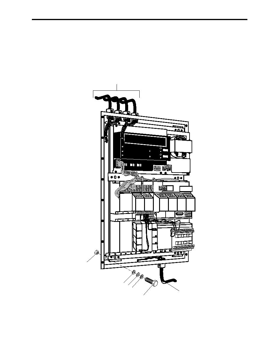
Figure 2. Fire and Smoke Detection Panel |
|
||
| ||||||||||
|
|
 TM 55-1925-292-14&P
0027 00
4. Remove the inboard 440 volt panel (figure 1, item 5) from the main switchboard (figure 1, item 3).
5. Label and remove all remaining electrical wiring (figure 2, item 1) from the enclosure.
6. Remove the six bolts (figure 2, item 2), six nuts (figure 2, item 3), 12 flat washers (figure 2, item 4), and six
lockwashers (figure 2, item 5). Discard the lockwashers.
7. Remove the fire and smoke detection panel from the main switchboard (figure 1, item 3).
1
MODEL CP-3
5 CONTROL
UNIT
POWER
GROUND
ALARM
FAULT
System 3
TROUBLE
AUDIBLE
CIRCUIT
RESET
ALARM
TROUBLE
LAMP TEST
SILENCE
SILENCE
MM-35
ZU-35
TL-30U
MM-35
BC-35
SR-32
3
4
4
5
1
2
Figure 2. Fire and Smoke Detection Panel
0027 00-3
|
|
Privacy Statement - Press Release - Copyright Information. - Contact Us |
