 |
|||
|
|
|||
|
Page Title:
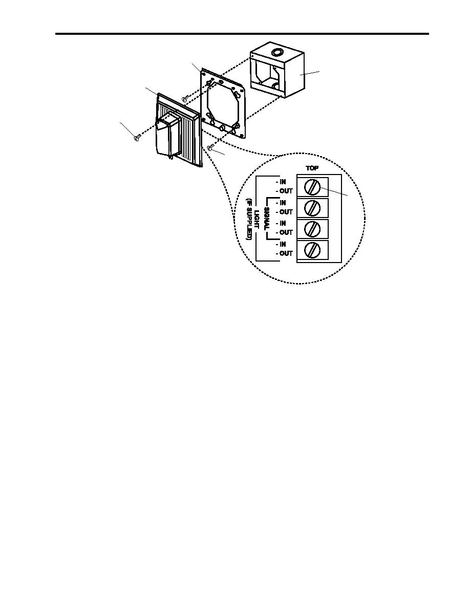
Figure 9. Horn/Strobe Replacement |
|
||
| ||||||||||
|
|
 TM 55-1925-292-14&P
0026 00
3
6
2
1
5
4
Figure 9. Horn/Strobe Replacement
INSTALLATION
1. Install the mounting plate (figure 9, item 3) to the junction box (figure 9, item 6) with the two screws (figure 9,
item 5).
2. Connect the wiring to the terminal board (figure 9, item 4) using the labels from step 3 of Removal as a guide.
Remove the labels.
3. Position the horn/strobe (figure 9, item 2) on the mounting plate (figure 9, item 3) and secure it with the two
screws (figure 9, item 1).
4. Perform the Follow-On Service procedure at the end of this work package.
ALARM BELL REPLACEMENT
REMOVAL
1. Remove the bolt (figure 10, item 1) and washer (figure 10, item 2) that secure the gong (figure 10, item 3).
2. Remove the gong (figure 10, item 3) from the bell actuator assembly cover (figure 10, item 4).
3. Remove the six screws (figure 10, item 5) that secure the bell actuator assembly cover (figure 10, item 4).
4. Remove the bell actuator assembly cover (figure 10, item 4), and turn it over to reveal the internal electrical
components (figure 10, item 6).
0026 00-11
|
|
Privacy Statement - Press Release - Copyright Information. - Contact Us |