 |
|||
|
|
|||
|
|
|||
| ||||||||||
|
|
 TM 55-1925-292-14&P
0026 00
INSTALLATION
1. Position the battery pack (figure 7, item 3) in the enclosure and secure it in place with the six screws
(figure 7, item 2).
2. Connect the electrical wiring to the terminal block (figure 7, item 1) using the labels from step 2 of Removal
as a guide. Remove the labels.
3. Perform the Follow-On Service procedure at the end of this work package.
RELAY MODULE SR-32 REPLACEMENT
REMOVAL
1. OPEN the enclosure following the Open Enclosure procedure of this work package.
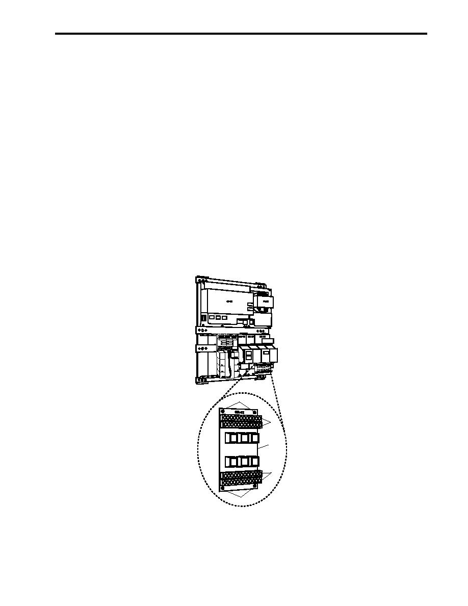
2. Label and disconnect the electrical wiring from the terminal blocks (figure 8, item 1).
3. Remove four screws (figure 8, item 2) that secure relay module SR-32 (figure 8, item 3), and remove it from
the enclosure.
2
1
3
1
2
Figure 8. Relay Module SR-32 Replacement
0026 00-9
|
|
Privacy Statement - Press Release - Copyright Information. - Contact Us |
