 |
|||
|
|
|||
|
Page Title:
DUAL ZONE MODULE ZU-35TS REPLACEMENT |
|
||
| ||||||||||
|
|
 TM 55-1925-292-14&P
0026 00
3. Connect the wiring to terminals 32 (figure 2, item 7), 35 (figure 2, item 8), and 41 (figure 2, item 9) using the
labels from step 4 of Removal as a guide. Remove the labels.
4. Connect the wiring plugs to connectors P1 (figure 2, item 4), P2 (figure 2, item 5), and P3 (figure 2, item 6).
5. Install the dust cover (figure 2, item 2), and secure it with the screws (figure 2, item 1).
6. Perform the Follow-On Service procedure at the end of this work package.
DUAL ZONE MODULE ZU-35TS REPLACEMENT
REMOVAL
1. OPEN the enclosure following the Open Enclosure procedure of this work package.
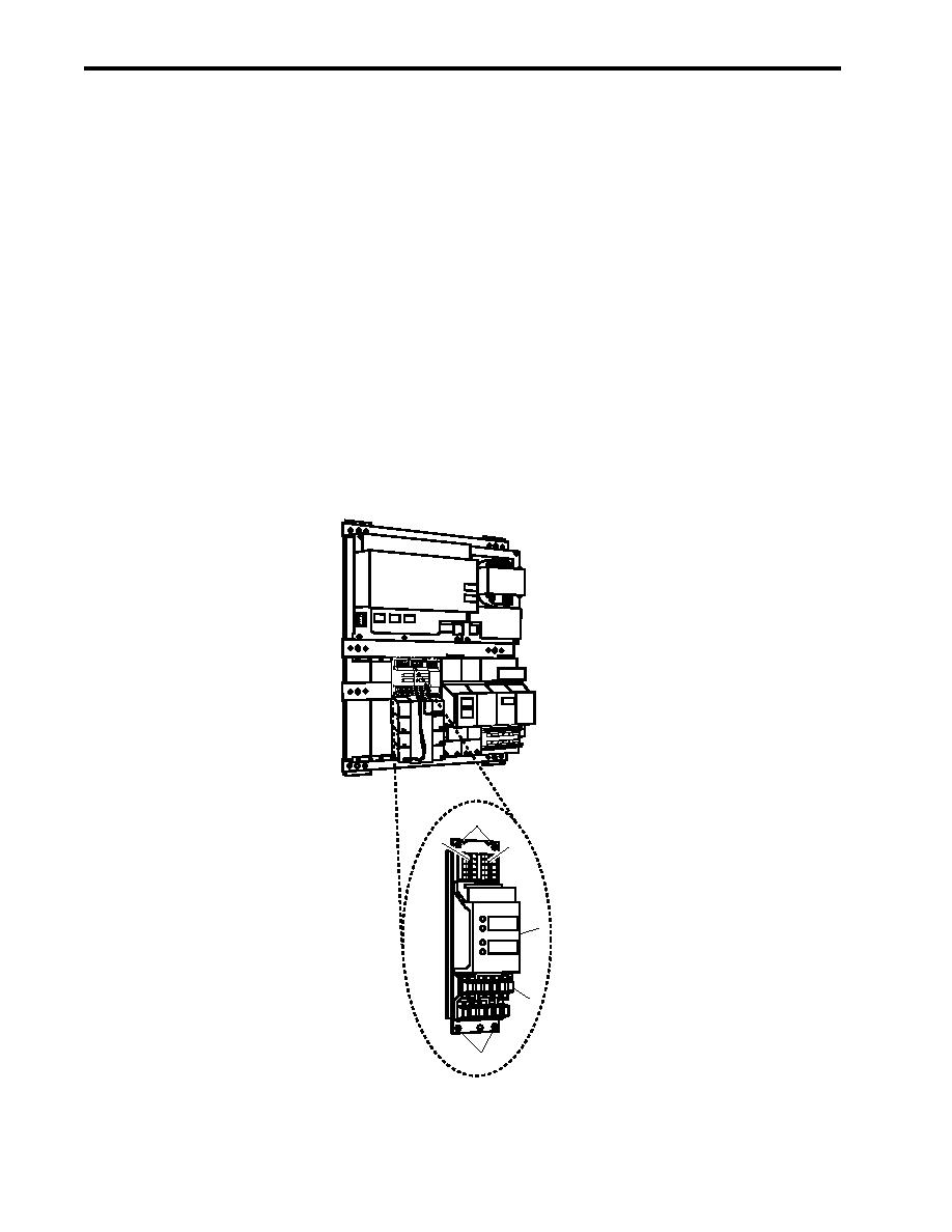
2. Label and disconnect the electrical wiring from P1 (figure 3, item 1), P2 (figure 3, item 2), and the terminal
block (figure 3, item 3).
3. Remove the four screws (figure 3, item 4) that secure the dual zone module ZU-35TS (figure 3, item 5), and
remove it from the enclosure.
CP-35
PS 35
MM-35
BE-35
BC-35
4
1
2
ZU-35
ZONE 1
5
03 & 02 LEVEL
ZONE 2
01 LEVEL
3
4
Figure 3. Dual Zone Module ZU-35TS Replacement
0026 00-4
|
|
Privacy Statement - Press Release - Copyright Information. - Contact Us |
