 |
|||
|
|
|||
|
|
|||
| ||||||||||
|
|
 TM 55-1925-292-14&P
0017 00
4. Reset the fire detection control panel (figure 2, item 3) by pressing the RESET LAMP TEST switch (figure 4,
item 4) on the CP-35 CONTROL UNIT (figure 4, item 2) momentarily and observe the following:
a. The audible alarm bell (figure 2, item 1) in the EOS sounds and all zone LEDs (figure 2, item 2) illuminate
on the fire detection panel (figure 2, item 3).
b. The audible alarm bell (figure 3, item 1) in the pilothouse sounds and all zone indicators (figure 3, item 2)
illuminate on the remote indicating panel (figure 3, item 3).
c.
The TROUBLE LED (figure 4, item 5) on the CP-35 CONTROL UNIT (figure 4, item 2) illuminates.
d. All audible alarms (figures 2 and 3 item 1) silence and all LEDs (figures 2 and 3, item 2 and figure 4,
items 3 and 5) extinguish.
e. The POWER FLASHING WHEN ON BATTERY LED (figure 4, item 6) is illuminated and not flashing.
f.
All zone LEDs (figure 2, item 2) on the fire detection panel (figure 2, item 3) are illuminated with the green
LED.
5. Perform the Follow-On Service procedure at the end of this work package.
THERMAL HEAT DETECTOR TESTING
NOTE
Prior to initiating the thermal heat detector test, notify the proper personnel that a test
will be performed so that any alarm soundings can be ignored during the test period.
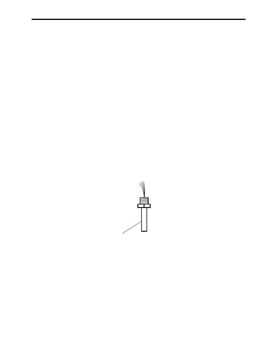
1. Activate a thermal heat detector (figure 5, item 1) using a heat gun and observe the following:
1
Figure 5. Thermal Heat Detector
NOTE
The fire detection panel has a green and red LED for each zone. The green LED indi-
cates the system is operating normally and the red LED indicates an abnormal condition
in the zone. A red LED requires an investigation by the crew to determine the cause of
the abnormal condition.
a. The audible alarm bell (figure 2, item 1) sounds in the Enclosed Operating Station (EOS) and the proper
zone LED (figure 2, item 2) illuminates on the fire detection panel (figure 2, item 3).
b. The audible alarm bell sounds in the pilothouse (figure 3, item 1) and the proper zone indicator (figure 3,
item 2) illuminates on the remote indicating panel (figure 3, item 3).
0017 00-5
|
|
Privacy Statement - Press Release - Copyright Information. - Contact Us |
