 |
|||
|
|
|||
|
Page Title:
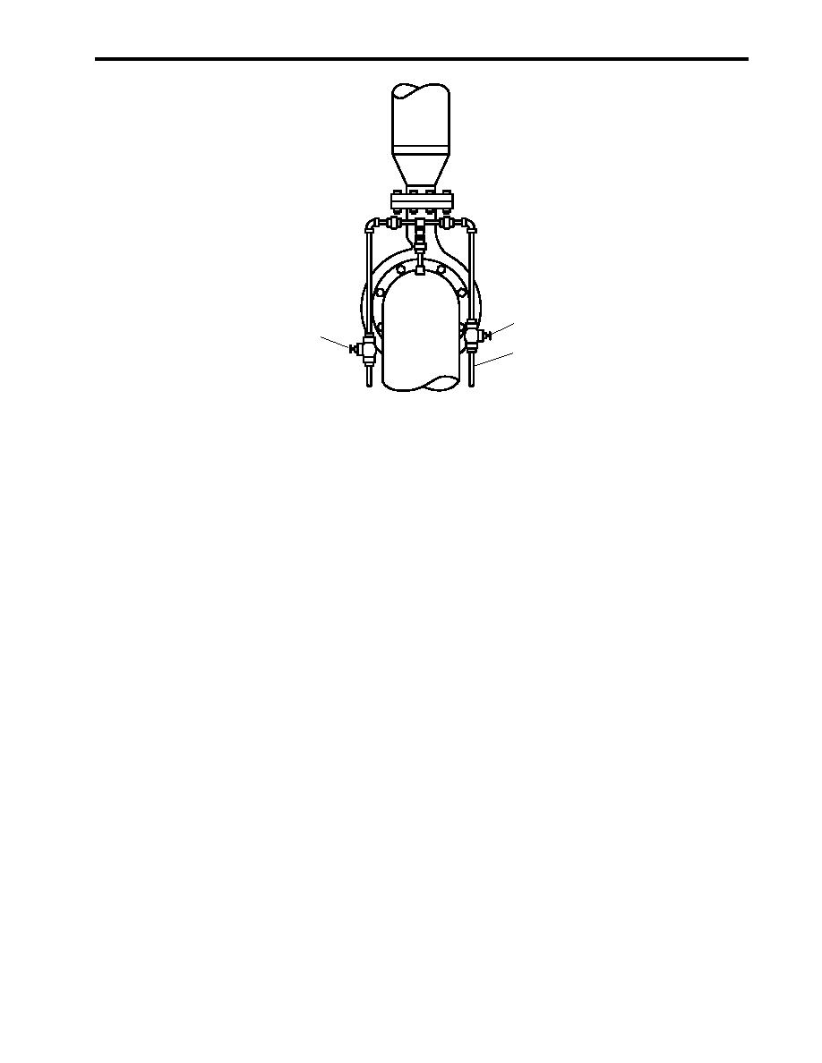
Figure 3. Diesel Engine-Driven Firefighting Pump Priming Valves |
|
||
| ||||||||||
|
|
 TM 55-1925-292-14&P
0006 00
1
2
3
Figure 3. Diesel Engine-Driven Firefighting Pump Priming Valves
FIRE MONITOR OPERATION WITH FIRE AND GENERAL SERVICE PUMPS
NOTE
In order to operate the fire monitors with the fire and general service pumps, both pumps
must be operating at full capacity. The operation of one fire monitor equals the full
capacity of both fire and general service pumps.
1. In the engine room, below the EOS, CLOSE FM-1, SEA SUCT, F.F. PMP.
2. In AMS 2, at the fire and general service pumps, OPEN the following valves:
a. FM-16, FIRE/G.S. NO.1 DISCH TO FM (figure 1, item 1)
b. FM-14, FIRE/G.S. NO.2 DISCH TO FM (figure 1, item 2)
3. START fire and general service pumps 1 and 2 (TM 55-1925-273-10).
4. OPEN FM-13, F.F. TO F.M. CRSVR (figure 2, item 2), fire pump to fire main cross connect.
5. Direct (aim) the fire monitor (figure 4, item 1) to place foam/water at the base of the fire.
6. OPEN the cutoff valve (figure 4, item 2) for the desired monitor.
7. When operation is complete:
a. CLOSE the cutoff valve (figure 4, item 2) for the monitor.
b. CLOSE FM-13, F.F. TO F.M. CRSVR (figure 2, item 2), fire pump to fire main cross connect.
c.
Return the fire and general service system to normal operation, and align the fire main to operate with the
standby fire and general service pump (TM 55-1925-273-10).
0006 00-3
|
|
Privacy Statement - Press Release - Copyright Information. - Contact Us |
