 |
|||
|
|
|||
|
Page Title:
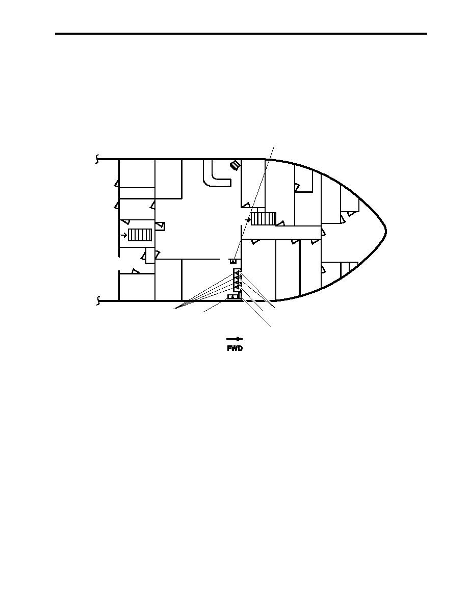
Figure 19. Galley Fire Suppression System |
|
||
| ||||||||||
|
|
 TM 55-1925-292-14&P
0003 00
Activation of the galley fire suppression system is accomplished manually by pulling the fire alarm pull
station (figure 19, item 1) or automatically by the melting of a fusible link (figure 19, items 2 and 3). Once the
system has been manually or automatically activated, the gas charge propels the extinguishing agent (figure 19,
item 4) to the distribution nozzles (figure 19, item 5). The electrical source for the protected equipment is not shut
off, and the agent and the hot grease mix to form foam. This foam temporarily seals the combustible vapors,
helping to inhibit re-ignition. The crew must secure the galley heat producing equipment. Once the galley fire
suppression system has been activated, the Gaylord washdown system (figure 19, item 6) is activated in the fire
cycle and sprays water into the Gaylord hood ventilation ductwork. Ventilation ducts are automatically secured by
the activation of the Gaylord washdown system.
1
D.C.
UP
LOCKER
CREW'S MESS/
BOATSWAIN'S
DN
RECREATION AREA
STORES
GALLEY
2
5
3
4
6
MAIN DECK
Figure 19. Galley Fire Suppression System
ARMS LOCKER DRENCHING SYSTEM
The arms locker drenching system is connected to the fire main system. The system is designed to provide raw
water to the arms locker in the event of a fire or excessive high temperatures. The arms locker drenching
system must be manually activated once the fire main has been charged. The system can be activated in the
boatswain's store (local) or from the 0-1 level (remote) at the bow by means of a reach rod valve system.
System activation occurs when the thermal heat detector (figure 20, item 1) senses a temperature above 105 F
(40.5 C). The thermal heat detector sends an alarm signal to the pilothouse indicating high temperature
conditions in the arms locker. The crew shall then investigate the situation and, if necessary, the fire main
system would be charged. Once it is determined that the alarm condition exists and the fire main system is
charged, the manual activation valve (figure 20, item 2) is OPENED either locally or remotely. As raw water
enters the piping system in the arms locker, a pressure switch (figure 20, item 3) activates an alarm in the
pilothouse to indicate that the arms locker drenching system has been activated. The raw water from the fire
main flows into the arms locker and out of two sprinkler heads (figure 20, item 4). Once activated, the system
will continue the flow of raw water into the arms locker until the manual activation valve is closed or the fire main
system is secured.
0003 00-21
|
|
Privacy Statement - Press Release - Copyright Information. - Contact Us |
