 |
|||
|
|
|||
|
Page Title:
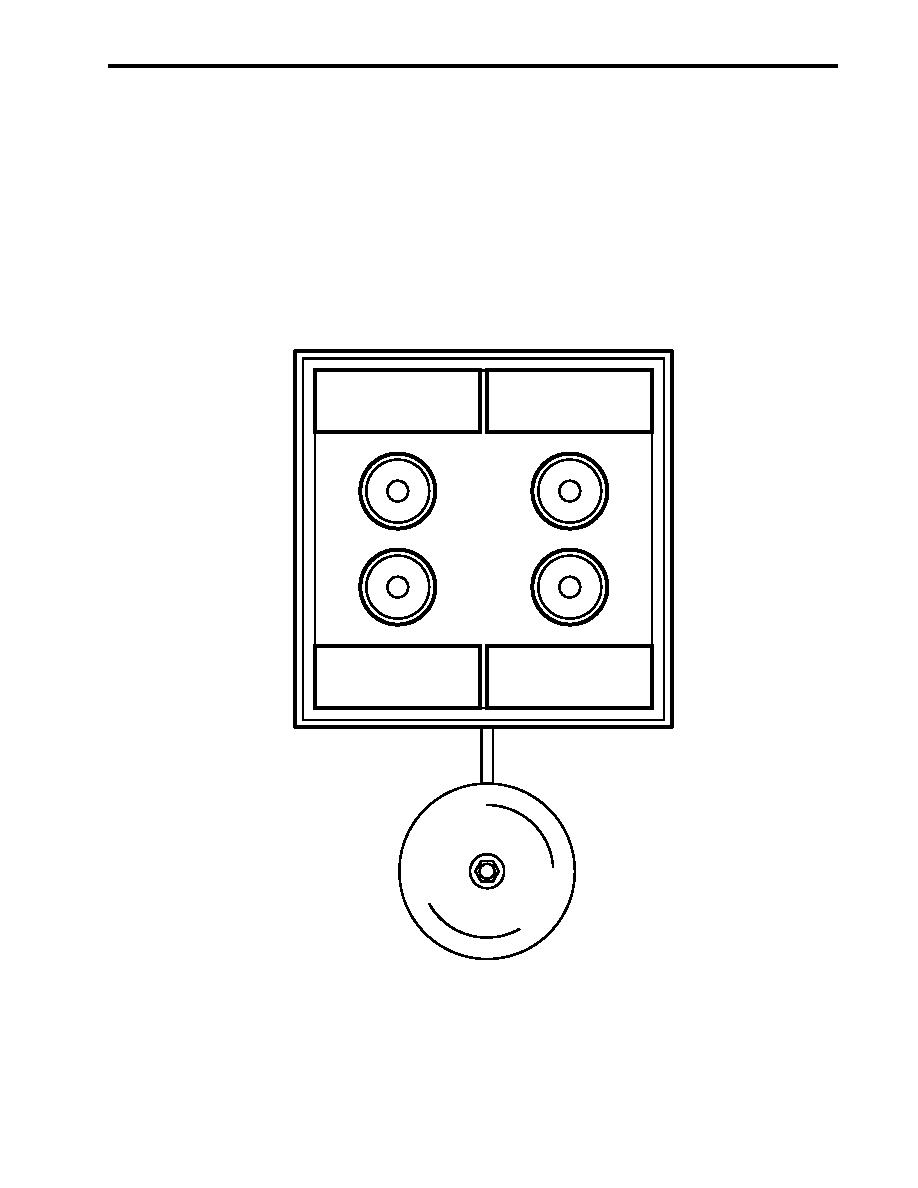
Figure 3. Fire Alarm System Remote Indicating Panel (Pilothouse) |
|
||
| ||||||||||
|
|
 TM 55-1925-292-14&P
0003 00
The fire and smoke detection panel also alerts the crew to any fire detector faults in the system. The fire and
smoke detection panel contains other indicators that illuminate during specific conditions. The POWER indica-
tor (figure 2, item 1) illuminates to indicate that normal power is being supplied to the fire and smoke detection
panel. It flashes when the fire and smoke detection panel is on battery power. The ALARM indicator (figure 2,
item 2) illuminates when the alarm is silenced. It flashes when an alarm condition exists but the alarm is
silenced. It will continue to flash as long as the audible alarm is silenced and an alarm condition is detected.
The TROUBLE indicator (figure 2, item 3) illuminates when the system detects a fault in the backup battery
system. The fire alarm system has its own backup battery in the fire and smoke detection panel. The DC
VOLTS meter (figure 2, item 4) measures the dc voltage available to the fire and smoke detection system, and
the DC AMPS meter (figure 2, item 5) indicates the dc current used by the alarm system. The voltage and
current indications are necessary in determining the status of the fire alarm system. If the TROUBLE indicator
illuminates and normal power is lost, the reliability of the fire alarm system may be suspect.
ZONE #1
ZONE #2
PILOTHOUSE, 02 LEVEL
01 LEVEL
ZONE #3
ZONE #4
MAIN DECK
HOLD LEVEL
Figure 3. Fire Alarm System Remote Indicating Panel (Pilothouse)
0003 00-3
|
|
Privacy Statement - Press Release - Copyright Information. - Contact Us |