
DRAFT
TM 5-4210-249-13&P-2
0178
MALFUNCTION
TEST OR INSPECTION
CORRECTIVE ACTION
TFFT03979
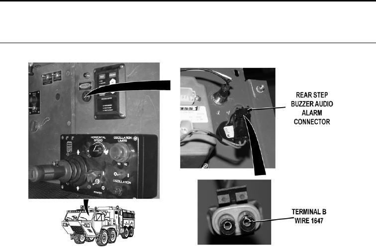
NOTE
Rear step buzzer indicator and audio alarm connectors are in contact with two separate
wire harnesses. Wire 1647 (brown) originates at cab power distribution wire harness and
introduces power into the circuit. Wire 1614 (brown) originates at main wire harness and
leads to rear step buzzer push button assembly through the driver side body wire harness.
Circuit is complete when rear step buzzer push button assembly is pushed, applying a
ground to circuit.
Step 4.
Install circuit breaker 7 (WP 0398). Remove personnel cab instrument panel
E (WP 0311). Disconnect rear step buzzer audio alarm connector. Turn battery
disconnect switch to ON position (WP 0007). With a test lead set, check for 22 to 28
VDC between cab power distribution wire harness wire 1647 (brown) at rear step
buzzer audio alarm connector, terminal B and a known good ground.
If 22 to 28 VDC are not present, repair wire 1647 in cab power distribution
wire harness if repairable (TM 9-2320-325-14&P), or replace cab power
distribution wire harness and block (WP 0441).
0178-4