|
| |
TM 5-4210-233-14&P-1
5-43. FORWARD TANDEM AXLE AND DRIVE UNIT-Continued
(12)
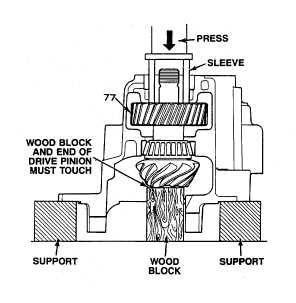
Reverse the differential carrier assembly (9) in the press so that threaded end of the drive pinion
(73) is toward top of press. Level carrier and place a wood block under head of drive pinion (73).
Press gear (77) onto pinion shaft with gear (77) contacts spacer (75).
(13)
Cut two pieces of teed or solder approximately 9/6 inch (14 mm) tong and 5/8 inch (16 mm) wide.
Use the two pieces as gauge blocks to determine thickness of spacer between helical gear (7) and
outer bearing cone (76). Place the pieces on top of the helical gear (77) so that they are opposite
each other.
(14)
Place outer bearing cone (76) in position on shaft. Use a sleeve and press bearing cone (76) down
on helical gear (77). Use two tons of pressure to press on bearing cone (76). The pressure wilt
compress the lead or solder pieces to correct size. Do not use more than two tons of pressure.
(15)
Release the pressure and remove wooden block from under head of drive pinion (73). Use a press
and sleeve to press the shaft of the drive pinion (73) out of the outer bearing cone. Do not press
the shaft of the drive pinion (73) out of the helical driven gear (77).
(16)
Remove the outer bearing cone (76) and two pieces of lead or solder from the outer bearing cone
(76). Use a micrometer to measure the thickness of the compressed pieces. Add the
measurements of the two pieces and divide by two to determine average size of pieces. Add 0.004
inch (0.100 mm) to the average size. Use this dimension to determine the size of the spacer (74)
to install between the outer bearing (76) and helical driven gear (77).
5-303
|