|
| |
TM 5-4210-233-14&P-1
5-39. STEERING GEAR
This task covers:
a.
Disassembly
d.
Adjustment
b.
Cleaning and Inspection
e.
Follow-on Maintenance
c.
Assembly
TOOLS REQUIRED:
EQUIPMENT CONDITION
Tool Kit, General Mechanics, Automotive
Main Engine Shutdown (see para 2-12.)
(Appendix B, Section III, Item 1)
APU Shutdown (see para 2-16.)
Batteries Disconnected (see para 4-114.)
MATERIALS/PARTS REQUIRED:
Steering Gear Removed (see para 4-161.)
Grease High Temperature (Item 15, Appendix E)
Tape, Masking (Item 52, Appendix E)
SPECIAL TOOLS REQUIRED:
Grease, Wheel Bearing (Item 53, Appendix E)
Compression Tool
O-rings (Fig. 158, Appendix F)
(Appendix B, Section III, Item 83)
Teflon washer (Fig. 158, Appendix F)
Seal Installation Tool
Seals (Fig. 158, Appendix F)
(Appendix B, Section III, Item 84)
Retainer (Fig. 158, Appendix F)
Bearing Mandrel
Vent Plug (Fig. 158, Appendix F)
(Appendix B, Section III, Item 88)
Gasket (Fig. 158, Appendix F)
Seal Driving Tool
Solvent, Dry cleaning (Item 3, Appendix E)
a.
Disassembly.
CAUTION
Clamp
only
against
housing
mounting bosses or attach a plate to
the
mounting
bosses
for
this
purpose. Do not clamp against the
body of housing.
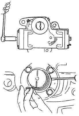
(1) Position the steering gear firmly in a vise
with the gear's worm shaft/input shaft (1) in a
horizontal direction. Prepare for fluid
drainage and unplug fluid line ports. Rotate
worm shaft/input shaft with a wrench,
through the gear travel several times to
purge hydraulic fluid from the unit. Then
position the timing mark located on the end
of the sector shaft (2) to a vertical direction.
5-216
|