|
| |
TM 5-4210-233-14&P-1
5-28. DDEC ELECTRONIC CONTROL MODULE AND SENSORS
This task covers:
a.
Electronic Control
c.
Turboboost Pressure Sensor
Wiring Harnesses
b.
DDEC Electronic
d.
Synchronous Reference Sensor
Control Module
(TRS)
e.
Follow-on Maintenance
TOOLS REQUIRED
EQUIPMENT CONDITION
Tool Kit, General Mechanics, Automotive
Main Engine Shutdown (see para 2-12.)
(Appendix B, Section III, Item 1)
APU Shutdown (see para 2-16.)
Batteries Disconnected (see para 4-114.)
MATERIALS/PARTS REQUIRED
Engine Cover Removed (see para 4-127.)
Lint Free Cloth (Item 42, Appendix E)
Driver Side Turbo Pipe Removed (see para 5-23.)
Seals (Fig. 128, Appendix F)
Driver Side Air Intake Removed (see para 5-1 1).
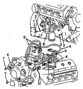
a.
Electronic Control Wiring Harnesses.
(1) Removal.
(a) Remove
screws
(1,
5
and
7),
lockwashers (2) and nut (3) to disengage
clamps.
(b) Remove any tie wraps as necessary to
free the harnesses.
(c) Disconnect wiring harness (6) from
control module and from sensors on
engine. Remove harness from engine.
(d) Disconnect harness (4) from control
module and from right bank of cylinder
head. Tag and disconnect harness wires
from engine brake retarder and injectors.
(e) Disconnect wiring harness (8) from
control module and from wiring harness
(11) at cab wail. Disconnect wiring
harness (11) from electronic unit in cab.
(f)
Disconnect wiring harness (9) from
control module and from wiring harness
(10) at cab wall. Disconnect wiring
harness (I0) from electronic unit in cab.
5-182
|