|
| |
TM 5-4210-233-14&P-1
5-23. TURBOCHARGER-Continued
(22)
Continue to tighten until the shaft increases in
length by .009-.010 of an inch. If measuring
equipment is not available, turn the nut an
additional 120°-130° (90° = 1/4 turn).
(23)
Place backplate (16) in vise with soft jaws.
(24)
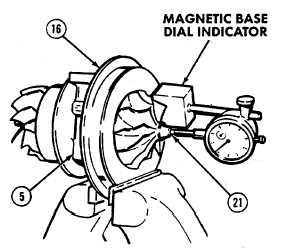
Check thrust float with dial indicator. Move shaft
(21) back and forth in center housing (5).
Indicator reading (thrust float) must be
0.003 to 0.010-in. (0.08 to 0.25 mm).
(25)
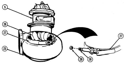
Align matchmarks on center housing (5) and turbine housing (25).
(26)
Install turbine wheel assembly (26) in turbine housing (25) and coupling (27).
(27)
Apply high temperature antiseize compound (Item 4, Appendix 4) to threads of screw (28).
CAUTION
Do not tighten turbine housing clamp until center housing is
aligned with turbine housing. If parts are not aligned, turbo-
charger will be damaged.
5-157
|