|
| |
TM 5-4210-233-14&P-1
5-21. BLOWER - Continued
(9)
Slip the snap ring (13) over the notched end of the alignment tool (Item 13, Section III,
Appendix B) and thread the blower drive shaft onto the end. Install the alignment tool and
position the blower so that the shaft can be removed and reinstalled easily without drag.
(10)
Remove the shaft with the tool and rotate the lobes of the blower in 900 increments, reinserting
the alignment tool and repositioning the blower as necessary. Check the alignment at 900
increments through the full 3600 of blower rotation.
(11)
If it is not possible to position the blower so that the tool can be removed and reinstalled
without drag in ail positions, repeat Step 10. However, this time try to achieve a condition in
which the shaft can be removed with minimum drag in the two worst positions.
(12)
Tighten four screws (7) to 40 to 45 lb-ft (54to 61 N.m).
(13)
Tighten six screws (9) in 5 Ib-ft (7 N.m) increments uniformly until tightened to 30 to 35 Ib-ft (41
to 47 N.m).
(14)
Retighten four screws (7) to 40 to 45 Ib-t (54 to 61 N.m).
(15)
Install the snap ring (13). The notch in the tool provides sufficient clearance for the installation
of the snap ring with a needle-nose pliers. Installing the snap ring with the alignment tool in
place will prevent it from being inadvertently dropped into the engine gear train.
(16)
Remove blower alignment tool.
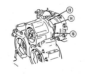
(17)
Position blower cover seal (14) on blower drive support (15).
(18)
Position clamp (16) in groove of seal (14). Tighten clamp until the spring in the clamp is
completely compressed.
5-120
|