|
| |
TM 5-4210-233-14&P-1
4-180. LADDER LOAD GAUGE
THIS TASK COVERS:
a.
Removal
c.
Follow-on Maintenance
b.
Installation
TOOLS REQUIRED
EQUIPMENT CONDITION
Tool Kit, General Mechanics, Automotive
Ladder Bedded (see para 2-14.)
(Appendix B, Section III, Item 1)
Main Engine Shutdown (see para 2-12.)
APU Shutdown (see para 2-16.)
MATERIALS/PARTS REQUIRED
Batteries Disconnected (see para 4-114.)
Pipe Sealant (Item 2, Appendix E)
Nylon Nuts (Figure 199, Appendix F)
a.
Removal.
(1) With engine off, operate ladder control
levers in both directions to relieve
hydraulic pressure in system.
(2) Open front door of control console.
NOTE
Tag all hose and tube assemblies before
disconnecting. Cap or plug all hose, tube, and
fitting openings to prevent entry of foreign
material.
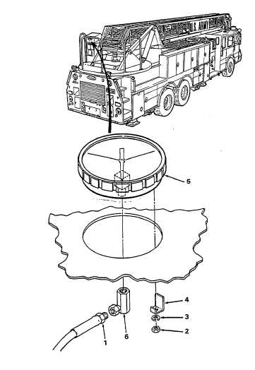
(3) Remove hydraulic hose (1). Cap hose
end.
(4) Remove two nylon nuts (2), two
lockwashers (3), two clamps (4), and
gauge (5).
(5) Remove fitting (6) from gauge (5).
b.
Installation.
(1) Install fitting (6) on gauge (5).
(2) Install gauge (5), two clamps (4), two
lockwashers (3) and two nylon nuts (2).
(3) Apply pipe sealant (Item 2, Appendix E)
to fitting (6).
(4) Install hydraulic hose (1).
(5) Close front door of control console.
4-469
|