|
| |
TM 5-4210-233-14&P-1
1-18. AERIAL LADDER/WATER TOWER. The firetruck is equipped with a hydraulic-powered, telescoping,
aerial ladder equipped with a remote nozzle.
a. Hydraulic System. The hydraulic system used to actuate the aerial ladder/water tower consists of the
following:
(1) A hydraulic reservoir with an internal filter.
(2) A pressure-compensated variable displacement hydraulic pump that is engine-driven via a power take-
off. A throttle control on the pump control panel controls engine speed during aerial operations.
(3) Each of the four outriggers use hydraulic cylinders for the extend/retract functions and for the
raise/lower functions. These functions are controlled by the outrigger cylinder controls located at the
back of the truck.
(4) The ladder hydraulics consist of the ladder lift cylinders, ladder extension retraction cylinders and a
turntable rotation motor and brake. The ladder hydraulic system is supplied by hydraulic lines that are
fed through a swivel to allow for continuous 360 degree rotation of the ladder. The truck has the ability
to operate all three ladder functions simultaneously with a minimum loss of speed or power.
(5) The turntable is rotated by a hydraulic motor with a planetary gear drive' assembly. A hydraulically-
released, spring-actuated brake provides positive stops of the aerial ladder rotation. The brake is
automatically disengaged by the same valve that controls the turntable rotation motor.
(6) For safety reasons, the outrigger hydraulic functions and the ladder hydraulic functions cannot be
operated at the same time. Hydraulic oil is either pumped to the outriggers or the ladder. This routing
of hydraulic oil is controlled by an electrically-actuated diverter valve operated from the outrigger
control panel on the back of the truck.
(7) The outriggers must be extended at least 18" and supporting the weight of the truck before the diverter
valve will direct oil flow to the ladder and make the ladder functions operable. Once the diverter valve
is switched to aerial operation, the outriggers cannot be operated until the ladder is in the bedded
position.
(8) In case of failure of the main hydraulic pump, an electrically powered back-up pump can be used. This
back-up pump is driven by a 12 VDC electric motor powered by the truck batteries. The emergency
pump provides for limited functions, and is activated by switches located on the outrigger and ladder
control panels.
1-19. AUXILIARY POWER CIRCUITS The auxiliary power circuit includes: the generator (auxiliary power unit
or APU), a load center, five 110-volt receptacle outlets and various switches and meters.
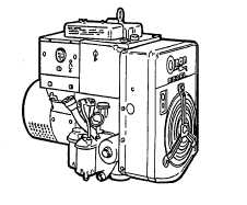
a. Auxiliary Power Unit (APU). The APU is a vertical four-stroke,
overhead-valve diesel engine. This air-cooled APU is equipped with
a governor to maintain constant speed and output. A 4-pole
regulated, self-excited generator serves as both a starting motor for
the diesel engine and the power source for the APU circuit. The
generator generates 110 VAC when the diesel engine is running. The
APU can be started from any one of three locations: the cab, the
street side pump panel or from the APU itself. The APU must be
preheated prior to starting. When the preheat switch is depressed, a
manifold heater heats the intake air in the engine manifold and a
glow plug heats the pre-combustion chamber.
1-20
|