|
| |
TM 5-4210-233-14&P-1
5-72. APU CYLINDER HEAD - Continued
(7)
Thoroughly clean the valve seat counterbore and remove any burrs from the edges. If the
counterbore is damaged, it will have to be remachined for an oversize seat. Oversize seats are
available in .002 in. (.051 mm), .005 in. (.127 mm), .010 in. (.254 mm) and .025 in. (.635 mm).
Otherwise, install new standard-size seat inserts.
(8)
Drive the new valve seat inserts into place. Be certain that each seat rests solidly on the bottom of
the counterbore at all points. To make installation easier, heat the cylinder head in an oven at
325°F (1 63 ºC) for about 30 minutes and cool the valve seats in dry ice.
(9)
Face each new seat to a 450 angle and width of 3/64 in. to 1/16 in. (1.19 to 1.59 mm). The finished
seat face should contact approximately center of the valve face. Use Marking Compound (Item 56,
Appendix E) on each valve face to check this. Make any corrections to the seat, not the valve
face.
(10)
When the new seats are installed and faced, insert the valve into each and check the clearance
from valve head to the face of the cylinder head. This must be at least .030 in. (.762 mm). If it is
not, regrind the seat.
(11)
Check the valve springs on an accurate compression scale. The valve spring load should register
45-49 Ibs. (20-22 kg) closed; 83-93 Ibs. (38-42 kg) open. Replace any weak, cracked or pitted
spring, or one that has out-of-square ends.
c.
Installation.
(1)
Push a valve stem oil sea[ (23) onto the intake valve guide (24) and clamp in place. Then oil (Item
10, Appendix E) the inside surface of the seal (15).
(2)
Oil (Item 1 0, Appendix E) the stem of each valve (25) lightly and insert into its own guide (24).
(3)
Check each valve (25) for a tight seat with an air pressure type tester. If a tester is not available,
use marking compound (Item 56, Appendix E) or make pencil marks at intervals on the valve face
and observe if the marks rub off uniformly when the valve is rotated part of a turn in the seat.
If the
seat is not tight, regrind the valves.
(4)
Using a valve spring compressor, compress each valve spring (22) and insert the valve spring
retainer (21) and retainer locks (20).
(5)
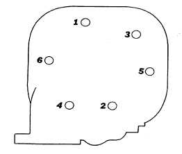
Install the head assembly (8) and gasket (8A) to the cylinder block. Tighten the head bolts (5 and
6) evenly to 44 to 46 ft. Ibs (60 to 62 N•m) in the proper sequence.
5-387
|